
Stick coils for the CBR1000F?


Banned
Joined: Jul 2012
Posts: 388
Likes: 0
From: Bottom of a Bottle in RI US
Thanks guys but I know what I'm talking about. I do have a EE degree. There is a delay in any mechanical device, relays have a mechanical switch powered by a coil. I appreciate you guys trying to explain but I'm talking about a very miniscule amount of time but one that will retard the spark because of it's inherent design.
Here:

This should explain my question better.
Here:
This should explain my question better.

Junior Member
Joined: Jun 2009
Posts: 25
Likes: 0
From: San Diego, CA
The relay mod is done to eliminate any voltage drops in the switched power circuit feeding constant 12VDC to the ignition circuit. I haven't seen a diagram for the Katana system that was referenced earlier, but in this diagram: 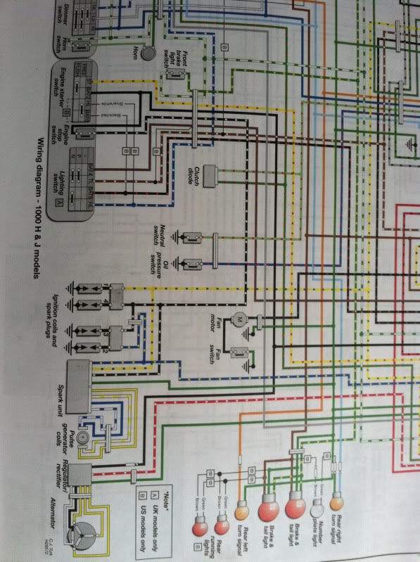
it looks like the black/white wire is the switched 12VDC. The coils are being supplied with constant power and the Pulse Generator Coils tell the Spark Unit which coil to connect to ground (green wire) at what time, thus causing the electrical field in the coil to collapse, thereby generating the huge voltage needed by the spark plugs. The relay would be on whenever the key was on so you wouldn't have to worry about the 3msec delay because it would only happen once, just as the key is switched on.
Your diagram shows a load supplied with intermittent power; whenever the horn button is pressed, there is a delay as the coil energizes and activates the switch in the relay, then the horn sounds. In our application the relay would be getting steady power and the "switching" happens downstream of the coils, so no delay after the initial triggering of the relay.
Banned
Joined: Jul 2012
Posts: 388
Likes: 0
From: Bottom of a Bottle in RI US
The relay mod is done to eliminate any voltage drops in the switched power circuit feeding constant 12VDC to the ignition circuit. I haven't seen a diagram for the Katana system that was referenced earlier, but in this diagram: {snip}
it looks like the black/white wire is the switched 12VDC. The coils are being supplied with constant power and the Pulse Generator Coils tell the Spark Unit which coil to connect to ground (green wire) at what time, thus causing the electrical field in the coil to collapse, thereby generating the huge voltage needed by the spark plugs. The relay would be on whenever the key was on so you wouldn't have to worry about the 3msec delay because it would only happen once, just as the key is switched on.
Your diagram shows a load supplied with intermittent power; whenever the horn button is pressed, there is a delay as the coil energizes and activates the switch in the relay, then the horn sounds. In our application the relay would be getting steady power and the "switching" happens downstream of the coils, so no delay after the initial triggering of the relay.

Member
Joined: Apr 2012
Posts: 52
Likes: 0
From: Dunedin, New Zealand
I also tried to point this out already earlier. The relay is NOT being switched in time with the pulse generator, it is only switching once at power on to supply +12 towards the coils. Completely agree.
Cheers
Kevin.


Member
Joined: Apr 2012
Posts: 52
Likes: 0
From: Dunedin, New Zealand
Hello K-TK, Yes almost - have been in the US for the last 5 weeks so am home now and completing some maintenance issues at the moment. Have just changed the CCT and done valve clearances (surprisingly EX were all good but the INs were tight as the proverbials proverbial). Also have done the coil stick mod. Still have to replace the vacuum line to the petcock, synch the carbs, fluids and filters and hopefully should be good to go before October.
I only got to do a few hundred Kms on the bike when I bought it before suspending the reg over winter, so am looking forward to giving it a good run.
Is everything good for you?
Cheers
Kevin
I only got to do a few hundred Kms on the bike when I bought it before suspending the reg over winter, so am looking forward to giving it a good run.
Is everything good for you?
Cheers
Kevin
Member
Joined: Apr 2012
Posts: 52
Likes: 0
From: Dunedin, New Zealand

Banned
Joined: Jul 2012
Posts: 388
Likes: 0
From: Bottom of a Bottle in RI US
 ) will indeed bypass the spark generator.
I believe The initial relay Mod I had found was more than likely a early mod that was improved with this one. Thanks for finally getting that into my thick skull.

BTW on your drawing for others that may read this and not know, Draw a box around the coil and switch and label for ease of reading. Unless you know how to read schematics those 2 have no reference to each other than K1 which really is not intuitive.
Well if nothing else I'm really glad you guys didn't give up on me because If I had done the original Mod and started having problems there is no way anyone could have figured out the issue!
I was also unaware that the pulse generators were nothing more than a completion to ground with a spark unit in between. I assumed it closed the circuit for the 12v to the coil, which I believe was the tap in the initial circuit I read. After going back to this diagram it makes perfect sense now.

Now I understand what CoolerThanElvis meant when he said " I haven't seen a diagram for the Katana system that was referenced earlier".
My apologies to all you guys. I can admit when I am wrong. Although we were talking about 2 different circuits. I was dumbfounded that you guys didn't get what I was saying so much that I missed the forest for the trees!