
build time! P=


Thread Starter
|
Senior Member
Joined: Dec 2013
Posts: 247
Likes: 11
From: Scotland
Thanks man. Gonna be a fun one when its finished. 
Speedo is almost wired just havent sorted tach or speed sensor yet. Headlight wired. Just brake and number plate light to do
Having a 'sympathy' flash situation with the indicators where they're all flashing at once if you signal left or right as the leds require so little to fire them. Havent yet wired resistors to cure the flash rate but i hope its enough to stop them all flashing. If not i'll have to wire diodes in. The speedo has diodes to seperate left and right circuit but it all flashes wether speedo is connected or not. Ill double check relay wiring too to confirm ive not wired it up daft. Its an issue ive heard of but never dealt with before
Welcome crew
Joined: Jan 2021
Posts: 2,568
Likes: 426
From: Preston, UK
It might be easier to just replace the flasher relay with and LED one rather than have individual diodes, I tried wired diodes and didn't really work (was for high flash rate admittedly), but LED Relay worked a treat
Thread Starter
|
Senior Member
Joined: Dec 2013
Posts: 247
Likes: 11
From: Scotland
the speedo im using has diodes built into its sub harness luckily which made the 4 way flashing with diodes in place... weird, initially i was second guessing my wiring having done the bike loom from scratch but its luckily come down to not enough load. wish i had a led relay sitting for a tidier job than the 4 resisters ive cable tied together in the tail but i keep a small stock of resistors haha
") something to redo over winter anyhooz, such a relief it was needing resistors as id have been doing anyway rather than a wiring or diode issues.
something to redo over winter anyhooz, such a relief it was needing resistors as id have been doing anyway rather than a wiring or diode issues.
Thread Starter
|
Senior Member
Joined: Dec 2013
Posts: 247
Likes: 11
From: Scotland
some progress pics

number plate light and indicators. may need to rethink plate light as its slightly intrusive.

cut down number plate bracket further and mounted the plate with adhesive pads. not sure it will fair but we'll see.

reassembled and just needing some wiring work now. pre indicator debacle. done for the night.
----

 [
[
surprisingly bright, possibly the brightest led indicators ive seen tbh.
amber led number plate bolts for indicators, alternatively ive used white led bolts in the past and wrapped them neatly with orange vinyl.
quite tricky getting micro indicators but this works well for me.

the ghetto resistor stack, luckily cured my 4 way flash (all flashing at once like hazard lights) situation. was wiring them to reduce flash rate before looking at other issue but wayhey sorted it.

front indicators on.
i noticed the rhs leds sit squint in their case but its minor, i might pick up another set of indicators over winter for and see if i get a straighter one for what little it matters.
---
so thats, the headlight, indicators, rear light, had to use some wrong colours to wire up the speedo / front parking light but i'll be redoing parts of the loom over winter and i'll address that properly.
i've managed to retain the factory speed sensor, im just going to have to figure out how many pickup points and a circumference that gives sensible speed readings. for reference anyone using the gearbox sensor with a aftermarket speedo (suitable for doing so) is use the signal cable from the gearbox in our case Pink, run it to the speedo and respectively run the positive reference and ground wires into the main wiring loom, not into the speedo. to reiterate, you only need the signal wire going to the speedo but the sensor needs power and ground.
i had concerns over sensor inputs as 2wire and 3wire sensors are completely different setups but if youre using a suitable speedo you can manipulate it to work.
its kind of funny, i made a nice custom loom to fit an alternative setup prior to deciding 600rr tail / this layout and ive had to hack into it do a couple of crappy things to get it going. acceptable, functional things but just not to a standard im happy leaving it at. plan is to see if i can squeeze all the electronics under the tank minus battery and drastically shorten the loom to aid weight savings and centeralise/lower centre of gravity over winter when its off the road.
--
current to do list:
i just need to hook electrics back up / cable tie and tidy
need to remove the ram air duct for repair as one of the inlets has come off slightly.
fit clips to the front mudguard to hold brake lines.
fit rear hugger back on
stash the shock reservoir somewhere
put some fuel in the tank and its good to go.
doing a radiator flush after first proper run.
its basically road ready at long last! after that it's coil over plug conversion to save weight, carbs jetted to suit exhaust and then look at whether i'll need to source a fuel pump or ill get away with staying gravity fed.
number plate light and indicators. may need to rethink plate light as its slightly intrusive.
cut down number plate bracket further and mounted the plate with adhesive pads. not sure it will fair but we'll see.
reassembled and just needing some wiring work now. pre indicator debacle. done for the night.
----
[surprisingly bright, possibly the brightest led indicators ive seen tbh.
amber led number plate bolts for indicators, alternatively ive used white led bolts in the past and wrapped them neatly with orange vinyl.
quite tricky getting micro indicators but this works well for me.
the ghetto resistor stack, luckily cured my 4 way flash (all flashing at once like hazard lights) situation. was wiring them to reduce flash rate before looking at other issue but wayhey sorted it.
front indicators on.
i noticed the rhs leds sit squint in their case but its minor, i might pick up another set of indicators over winter for and see if i get a straighter one for what little it matters.
---
so thats, the headlight, indicators, rear light, had to use some wrong colours to wire up the speedo / front parking light but i'll be redoing parts of the loom over winter and i'll address that properly.
i've managed to retain the factory speed sensor, im just going to have to figure out how many pickup points and a circumference that gives sensible speed readings. for reference anyone using the gearbox sensor with a aftermarket speedo (suitable for doing so) is use the signal cable from the gearbox in our case Pink, run it to the speedo and respectively run the positive reference and ground wires into the main wiring loom, not into the speedo. to reiterate, you only need the signal wire going to the speedo but the sensor needs power and ground.
i had concerns over sensor inputs as 2wire and 3wire sensors are completely different setups but if youre using a suitable speedo you can manipulate it to work.
its kind of funny, i made a nice custom loom to fit an alternative setup prior to deciding 600rr tail / this layout and ive had to hack into it do a couple of crappy things to get it going. acceptable, functional things but just not to a standard im happy leaving it at. plan is to see if i can squeeze all the electronics under the tank minus battery and drastically shorten the loom to aid weight savings and centeralise/lower centre of gravity over winter when its off the road.
--
current to do list:
i just need to hook electrics back up / cable tie and tidy
need to remove the ram air duct for repair as one of the inlets has come off slightly.
fit clips to the front mudguard to hold brake lines.
fit rear hugger back on
stash the shock reservoir somewhere
put some fuel in the tank and its good to go.
doing a radiator flush after first proper run.
its basically road ready at long last! after that it's coil over plug conversion to save weight, carbs jetted to suit exhaust and then look at whether i'll need to source a fuel pump or ill get away with staying gravity fed.
Last edited by iamhiding; Sep 18, 2021 at 07:24 PM.
Thread Starter
|
Senior Member
Joined: Dec 2013
Posts: 247
Likes: 11
From: Scotland
amazing how long it took to do so but wiring is now all loosely cable tied and routed.
really not happy with having to ram all the connector blocks in below the carbs for now though. that was quite a task due to needing to connect it all up under the carbs with zero space to do so.
as to why, well if run it above it clutters up the area behind the carbs which is semi visible until i make infill panels round the tank and seat / exposed connectors directly under the petcock is eh... just not wise.

speedo in place, wired up and most of the settings dialled in.
there's very little helpful info available on setting up speedo to vss other than people opting to use the often supplied hall effect sensors you slap beside the wheel etc and fire some magnets on. i figure this may help someone in the future.
in terms of speed intput from the honda vss i've got it mostly sussed. its similar to setting up a basic 2wire hall effect sensor and x amount of magnets to brake disk etc in that you tell the speedo how many pulses occur over the space of a single wheel rotation and the circumference of your tyre.
so theres a couple of ways of measuring circumference however the easiest is multiplying the diameter by pi. so in my case on the temp 180/55 roughly 630mm diamater x pi 3.14 = 1978mm. im happy enough with a rough measurement as circumference changes with tyre pressure, therefor temperature changes it and you can also throw in that centrifugal forces cause the tyres to balloon the faster they spin too... so ballpark is fine. i believe factory speedos are or certainly used to be allowed to read up to 14% high.
for calculating pulses we need to know final drive ratio, in my case im using 15/45 sprockets and 45 divided by 15 = 3. meaning that its a 3:1 ratio in that the front sprocket rotates 3 times for the rear wheel to rotate once.
vss takes on/off pulses from the gearbox, i believe it can either have a dedicated trigger wheel if for some reason they cant use a gear but on the f3 its off of a gear on the countershaft. best thing to do is measure pulses manually by rotating the either the wheel a full turn and counting pulses or alternatively the front sprocket a full turn and multiplying the result by final drive.
bit of a tangent but in researching this ive read that the 900rr uses 5th gear on the countershaft making it 28t therefor 28 pulses however having looked at the parts fiche and gearbox specs its actually 27t anyway... other than this one place citing the 900rr uses 5th i've got no evidence to substantiate it. i was hoping that i could base the assumption that the f3 used 5th too, even so manually counting or well executed trial and error are the most sensible approach. i also read that the 900rr gives out 4 pulses per rotation on mph speedos and that kmh bikes are 3 pulse but... it seems to be speculative nonsense given how the sensor picks up teeth on the gear. my point is just because you read something on the internet thats technical beyond your current understanding and it sounds right / plausible it's still just an interpretation on the internet. likewise take my understanding, experience and explanation for what it is, relatively inexperienced as im not an engineer.
given how awkward it is to check pulses manually i'm opting to take the tactful trial and error approach, i'm fairly confident the sensor will be counting from 5th or 6th on the countershaft so first ill try the teeth count from 5th and then 6th to see which renders a closer result to gps accuracy on my phone. countershaft 5th being 24t and countershaft 6th being 25t which are obviously quite close and likely difficult to differentiate but we shall see.
anyway. you need to take final drive into consideration and assuming its 24t in my case, thats 24 pulses per front sprocket rotation multiplied by the final drive of 3 gives me 72 pulses per rotation of the rear wheel. basing it on 6th, 25x3 would be 75 pulses alternatively.
once i've got solid evidence so support my method ill try fire up a dedicated post to it as if i couldve found all this info in one place itd have saved me a massive chunk of time researching it.
-------

dropped the radiator to get the ram air duct out again, pressed the tube back in an gave it a lick of silicone. whilst curing i refitted the rear hugger and go to insulating / tiying the wiring further.


all the wires from the from the front run down either side of the carbs under the ram air hoses to the float bowls. also used a smaller filter pre carb on the rhs.
going to need to pull the airbox off again as i think wires underneath may be making it difficult to connect the ram air duct to the box.


need to square everything up straight and tuck it here and there but thats my routing for now and it'll do but damn im not liking the way ive had to do it. the tank nestles down well into everything which is a relief however i put a few litres in the tank and i turns out my petcock leaks, got a spare to go on though, all going well i'll get the bike road ready tomrrow.
current to do list:
i just need to hook electrics back up / cable tie and tidy
need to remove the ram air duct for repair as one of the inlets has come off slightly.
fit clips to the front mudguard to hold brake lines.
tighten up switchgear controls on the bars
fit rear hugger back on
stash the shock reservoir somewhere
put some fuel in the tank and its good to go. ~ replace leaky petcock. should have a spare one though.
doing a radiator flush after first proper run.
really not happy with having to ram all the connector blocks in below the carbs for now though. that was quite a task due to needing to connect it all up under the carbs with zero space to do so.
as to why, well if run it above it clutters up the area behind the carbs which is semi visible until i make infill panels round the tank and seat / exposed connectors directly under the petcock is eh... just not wise.
speedo in place, wired up and most of the settings dialled in.
there's very little helpful info available on setting up speedo to vss other than people opting to use the often supplied hall effect sensors you slap beside the wheel etc and fire some magnets on. i figure this may help someone in the future.
in terms of speed intput from the honda vss i've got it mostly sussed. its similar to setting up a basic 2wire hall effect sensor and x amount of magnets to brake disk etc in that you tell the speedo how many pulses occur over the space of a single wheel rotation and the circumference of your tyre.
so theres a couple of ways of measuring circumference however the easiest is multiplying the diameter by pi. so in my case on the temp 180/55 roughly 630mm diamater x pi 3.14 = 1978mm. im happy enough with a rough measurement as circumference changes with tyre pressure, therefor temperature changes it and you can also throw in that centrifugal forces cause the tyres to balloon the faster they spin too... so ballpark is fine. i believe factory speedos are or certainly used to be allowed to read up to 14% high.
for calculating pulses we need to know final drive ratio, in my case im using 15/45 sprockets and 45 divided by 15 = 3. meaning that its a 3:1 ratio in that the front sprocket rotates 3 times for the rear wheel to rotate once.
vss takes on/off pulses from the gearbox, i believe it can either have a dedicated trigger wheel if for some reason they cant use a gear but on the f3 its off of a gear on the countershaft. best thing to do is measure pulses manually by rotating the either the wheel a full turn and counting pulses or alternatively the front sprocket a full turn and multiplying the result by final drive.
bit of a tangent but in researching this ive read that the 900rr uses 5th gear on the countershaft making it 28t therefor 28 pulses however having looked at the parts fiche and gearbox specs its actually 27t anyway... other than this one place citing the 900rr uses 5th i've got no evidence to substantiate it. i was hoping that i could base the assumption that the f3 used 5th too, even so manually counting or well executed trial and error are the most sensible approach. i also read that the 900rr gives out 4 pulses per rotation on mph speedos and that kmh bikes are 3 pulse but... it seems to be speculative nonsense given how the sensor picks up teeth on the gear. my point is just because you read something on the internet thats technical beyond your current understanding and it sounds right / plausible it's still just an interpretation on the internet. likewise take my understanding, experience and explanation for what it is, relatively inexperienced as im not an engineer.
given how awkward it is to check pulses manually i'm opting to take the tactful trial and error approach, i'm fairly confident the sensor will be counting from 5th or 6th on the countershaft so first ill try the teeth count from 5th and then 6th to see which renders a closer result to gps accuracy on my phone. countershaft 5th being 24t and countershaft 6th being 25t which are obviously quite close and likely difficult to differentiate but we shall see.
anyway. you need to take final drive into consideration and assuming its 24t in my case, thats 24 pulses per front sprocket rotation multiplied by the final drive of 3 gives me 72 pulses per rotation of the rear wheel. basing it on 6th, 25x3 would be 75 pulses alternatively.
once i've got solid evidence so support my method ill try fire up a dedicated post to it as if i couldve found all this info in one place itd have saved me a massive chunk of time researching it.
-------
dropped the radiator to get the ram air duct out again, pressed the tube back in an gave it a lick of silicone. whilst curing i refitted the rear hugger and go to insulating / tiying the wiring further.
all the wires from the from the front run down either side of the carbs under the ram air hoses to the float bowls. also used a smaller filter pre carb on the rhs.
going to need to pull the airbox off again as i think wires underneath may be making it difficult to connect the ram air duct to the box.
need to square everything up straight and tuck it here and there but thats my routing for now and it'll do but damn im not liking the way ive had to do it. the tank nestles down well into everything which is a relief however i put a few litres in the tank and i turns out my petcock leaks, got a spare to go on though, all going well i'll get the bike road ready tomrrow.
current to do list:
fit clips to the front mudguard to hold brake lines.
tighten up switchgear controls on the bars
stash the shock reservoir somewhere
doing a radiator flush after first proper run.
Thread Starter
|
Senior Member
Joined: Dec 2013
Posts: 247
Likes: 11
From: Scotland
turned into a bit of a hectic evening of it, just chasing little issues and it being a muck about. anyway, some progress pics.
was having to cross the clutch switch and keep the sidestand up to start the bike for a couple of years, i had tested and replaced the clutch switch a few weeks ago but was still only running with stand up, wasnt bothered by it as i was elbow deep in more important jobs on it. after getting round to fitting the gauge i realized my neutral switch had failed which i just got around by grounding it out at the time and i realised that whilst in gear the neutral light came on the speedo with the clutch pulled in, an indication the clutch switch diode had an issue too. so earlier i pulled the neutral switch out, tested it and the cable again to be sure and right enough switch had failed, replaced it with a spare, confirmed it was working and that the light was coming on with the clutch lever still, it was so i replaced the diode with a spare and all is right with the world again haha. but yeah so failed clutch switch, neutral switch and clutch switch diode all at the same time. think it just goes to show how much bikes dont like being parked up for years because what are the chances, i'm just glad i know my way around these issues, it could really stump someone.

the bundle of cables taking up space and causing issue with the airbox not joining to the ram air section well. the big loop is the thermal sensor extension for the acewell speed and i suspect to be the biggest culprit.

wedged as much as i could out to the sides and it fits significantly better. when i replace the oldschool coils for coil over plugs it'll free up that area for space. ive also blanked off the hole for the rocker cover breather into the airbox so it wont be recirculating hot oily air. after putting it all back together realised cables pulled tight when bars were were turned to the right and the throttle was binding slightly too, ripped connectors off of the indicator by accident so had to pull it apart and deal with all that again.

clutter under here is unmanageable haha its going to be a niiiiightmare if i need to unplug anything before its redone properly.

fitted the horn in here.

and soon remembered that you cant have anything there cuz' the petcock sits in there. its why i've routed the wiring loom so awkwardly underneath it all as well. it'll be much tidier once i get round to making side panels and i can re-route. forgot to grab a pic but ive attached the horn to the old side panel mount at the bottom of this pic.

what a mess haha but yeah shock reservoir sits up in here alright, tried to stash it in the side of the tail but its just not feasible with how everything fits together. going to need to fit an inline fuse beside the battery for the main power cable to the starter solenoid as the solenoid is under the tank / the battery is in the tail and should that long cable short anywhere... ima be in trouble with that battery.
basically just need to give the bike a once over, fit clips for the brake lines to the front mudguard, an inline fuse on that battery positive and give the bike a clean down and its good to go.
current to do list:
i just need to hook electrics back up / cable tie and tidy
need to remove the ram air duct for repair as one of the inlets has come off slightly.
fit clips to the front mudguard to hold brake lines.
inline battery pos fuse.
tighten up switchgear controls on the bars
fit rear hugger back on
stash the shock reservoir somewhere
put some fuel in the tank and its good to go.
replace leaky petcock.
doing a radiator flush after first proper run.
was having to cross the clutch switch and keep the sidestand up to start the bike for a couple of years, i had tested and replaced the clutch switch a few weeks ago but was still only running with stand up, wasnt bothered by it as i was elbow deep in more important jobs on it. after getting round to fitting the gauge i realized my neutral switch had failed which i just got around by grounding it out at the time and i realised that whilst in gear the neutral light came on the speedo with the clutch pulled in, an indication the clutch switch diode had an issue too. so earlier i pulled the neutral switch out, tested it and the cable again to be sure and right enough switch had failed, replaced it with a spare, confirmed it was working and that the light was coming on with the clutch lever still, it was so i replaced the diode with a spare and all is right with the world again haha. but yeah so failed clutch switch, neutral switch and clutch switch diode all at the same time. think it just goes to show how much bikes dont like being parked up for years because what are the chances, i'm just glad i know my way around these issues, it could really stump someone.
the bundle of cables taking up space and causing issue with the airbox not joining to the ram air section well. the big loop is the thermal sensor extension for the acewell speed and i suspect to be the biggest culprit.
wedged as much as i could out to the sides and it fits significantly better. when i replace the oldschool coils for coil over plugs it'll free up that area for space. ive also blanked off the hole for the rocker cover breather into the airbox so it wont be recirculating hot oily air. after putting it all back together realised cables pulled tight when bars were were turned to the right and the throttle was binding slightly too, ripped connectors off of the indicator by accident so had to pull it apart and deal with all that again.
clutter under here is unmanageable haha its going to be a niiiiightmare if i need to unplug anything before its redone properly.
fitted the horn in here.
and soon remembered that you cant have anything there cuz' the petcock sits in there. its why i've routed the wiring loom so awkwardly underneath it all as well. it'll be much tidier once i get round to making side panels and i can re-route. forgot to grab a pic but ive attached the horn to the old side panel mount at the bottom of this pic.
what a mess haha but yeah shock reservoir sits up in here alright, tried to stash it in the side of the tail but its just not feasible with how everything fits together. going to need to fit an inline fuse beside the battery for the main power cable to the starter solenoid as the solenoid is under the tank / the battery is in the tail and should that long cable short anywhere... ima be in trouble with that battery.
basically just need to give the bike a once over, fit clips for the brake lines to the front mudguard, an inline fuse on that battery positive and give the bike a clean down and its good to go.
current to do list:
fit clips to the front mudguard to hold brake lines.
inline battery pos fuse.
doing a radiator flush after first proper run.
Last edited by iamhiding; Sep 20, 2021 at 08:43 PM.
Thread Starter
|
Senior Member
Joined: Dec 2013
Posts: 247
Likes: 11
From: Scotland

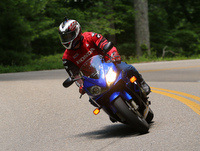
sneak peak of the bike. looks better in the flesh and i really need to paint the front disc carriers and headlight brackets black.
wee update as its been a while again. got the bike "finished up" into a road ready state ready for mot. went to insure it and realized the admin fees alone were almost as much as a full years policy to add it to my current policy ending in december... then realized i had about 9 days before the 1st of oct when gritters go on hold in the uk for winter... so it was going to cost a fortune for a few weeks riding and decided i'd leave it till spring. good thing is it gives my some time over winter to redo my rushed wiring, make side panels and generally sort out some little things. going to have a look at fitting the alloy swingarm when i get the time too.
possibly sussed out my non matching wheel conundrum. i had originally planned on using the f4i rear wheel to have matching 3 spokes front and rear, being honest i love the honda 6 spoke wheels and theres some complexity to how thin the f4i sprocket carrier is and removing material to help get it in line with the front is going to be tight, even with spacing the front out. id love to keep the f3 rear wheel and i've found that the sp1 vtr 1000 front wheel can be used on the 929/954 fork assembly with some minor work which would give me matching true to the era. the downside being sp1 wheels are... rare and therefor expensive when they turn up.

