
'93 600 Fighter project

Thread Starter
|
July 2011 ROTM
Joined: May 2010
Posts: 223
Likes: 8
From: Hampton Roads, VA
finally got some pictures up!
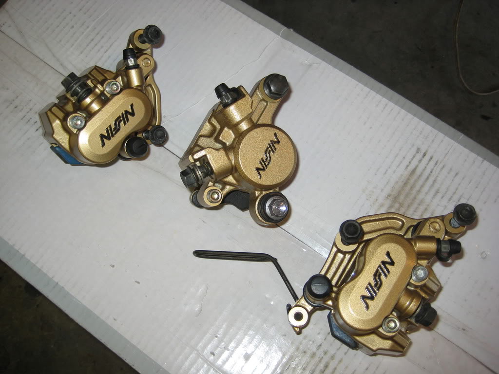
I rebuilt the brakes...
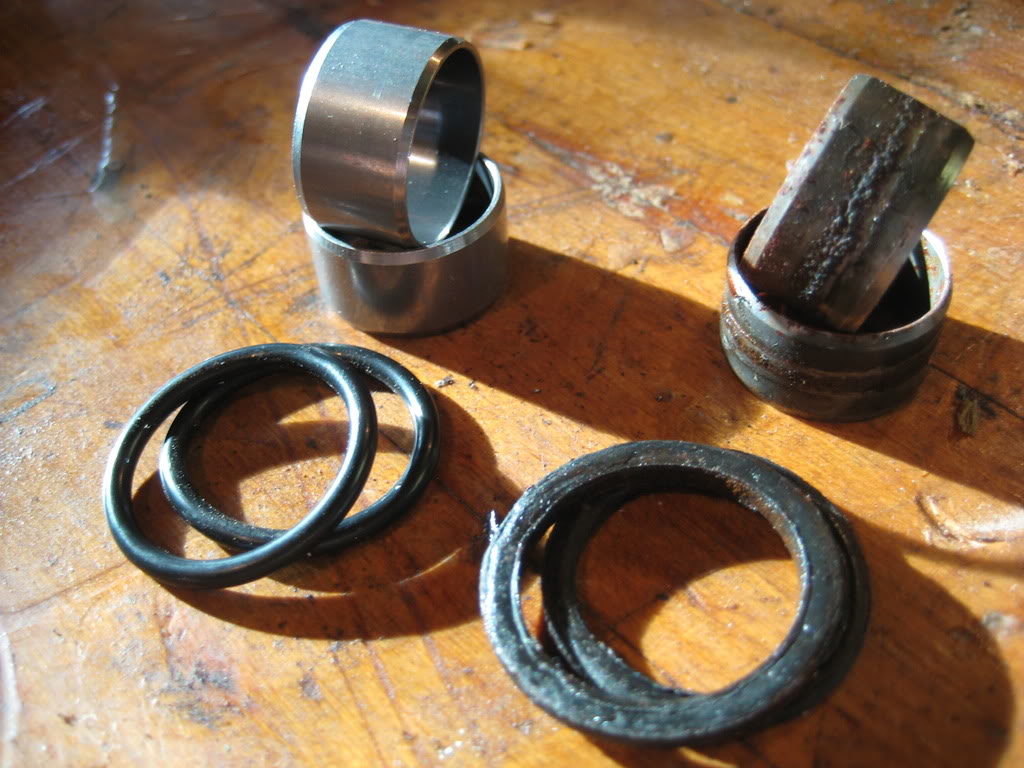
The old vs. new oil cooler collars/o-rings
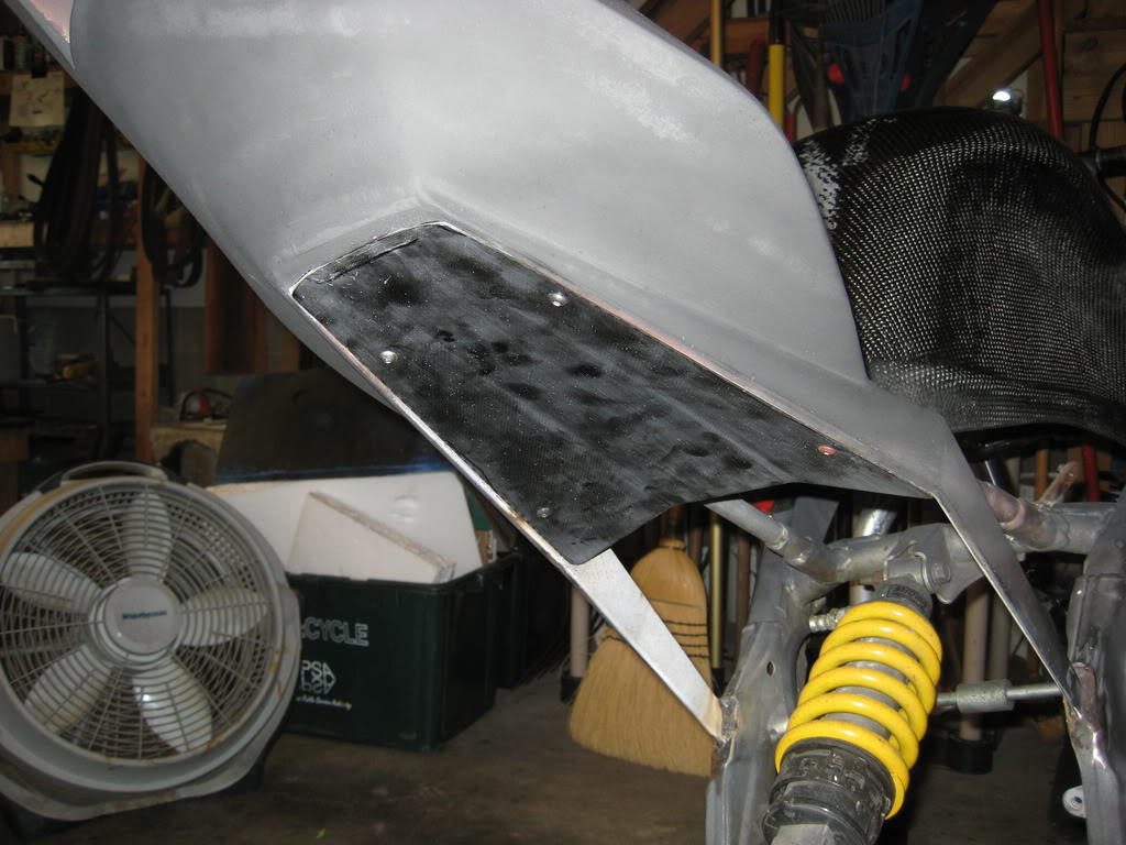
installed the undertail (it still need a bit of final trimming)
and sanded the tank.. hello lung failure
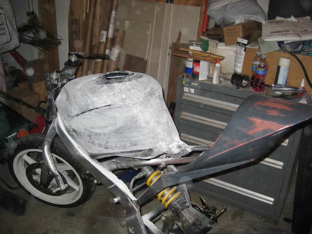
all down to 220 and i have almost all the low spots out.
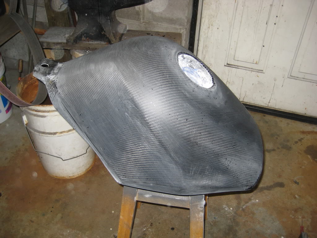
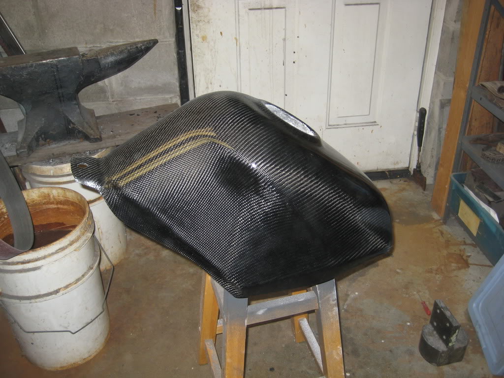
And.... i had to put a bit of clear on there to see how it turned out. looking better! :rock:
well i am hoping to get some more done tommorow. i finally got some plasti-gauge, so i hope to start putting the engien back together, and i also am getting the tail ready for CF
more later!
~Chris
I rebuilt the brakes...
The old vs. new oil cooler collars/o-rings
installed the undertail (it still need a bit of final trimming)
and sanded the tank.. hello lung failure
all down to 220 and i have almost all the low spots out.
And.... i had to put a bit of clear on there to see how it turned out. looking better! :rock:
well i am hoping to get some more done tommorow. i finally got some plasti-gauge, so i hope to start putting the engien back together, and i also am getting the tail ready for CF
more later!
~Chris
Thread Starter
|
July 2011 ROTM
Joined: May 2010
Posts: 223
Likes: 8
From: Hampton Roads, VA
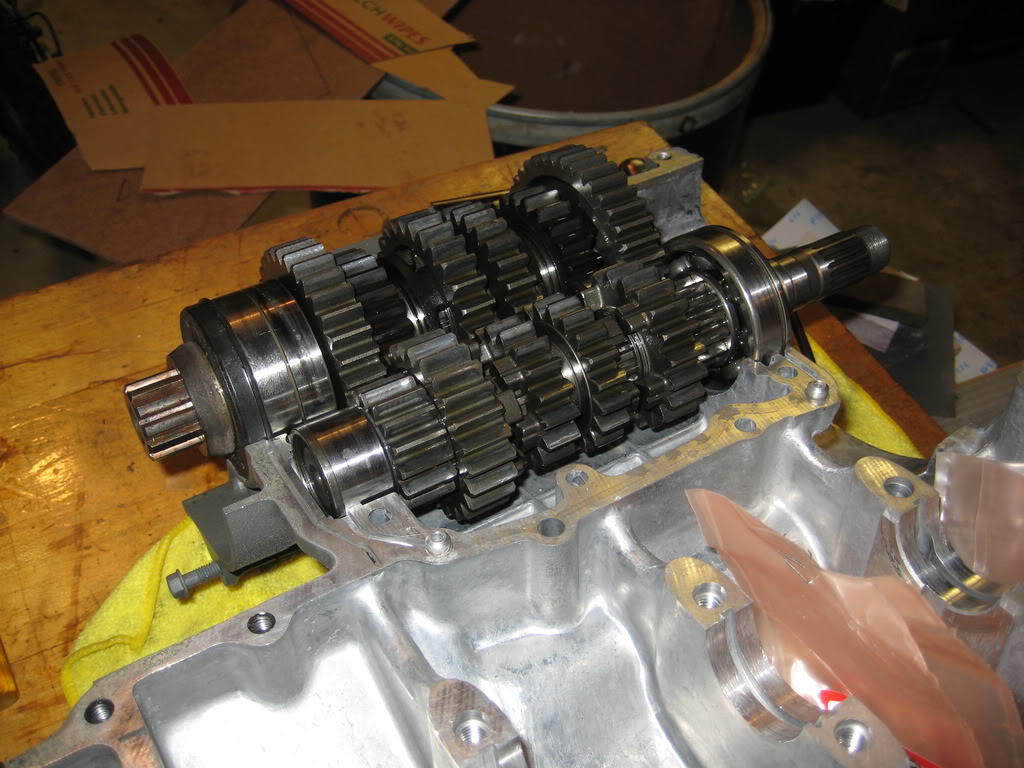
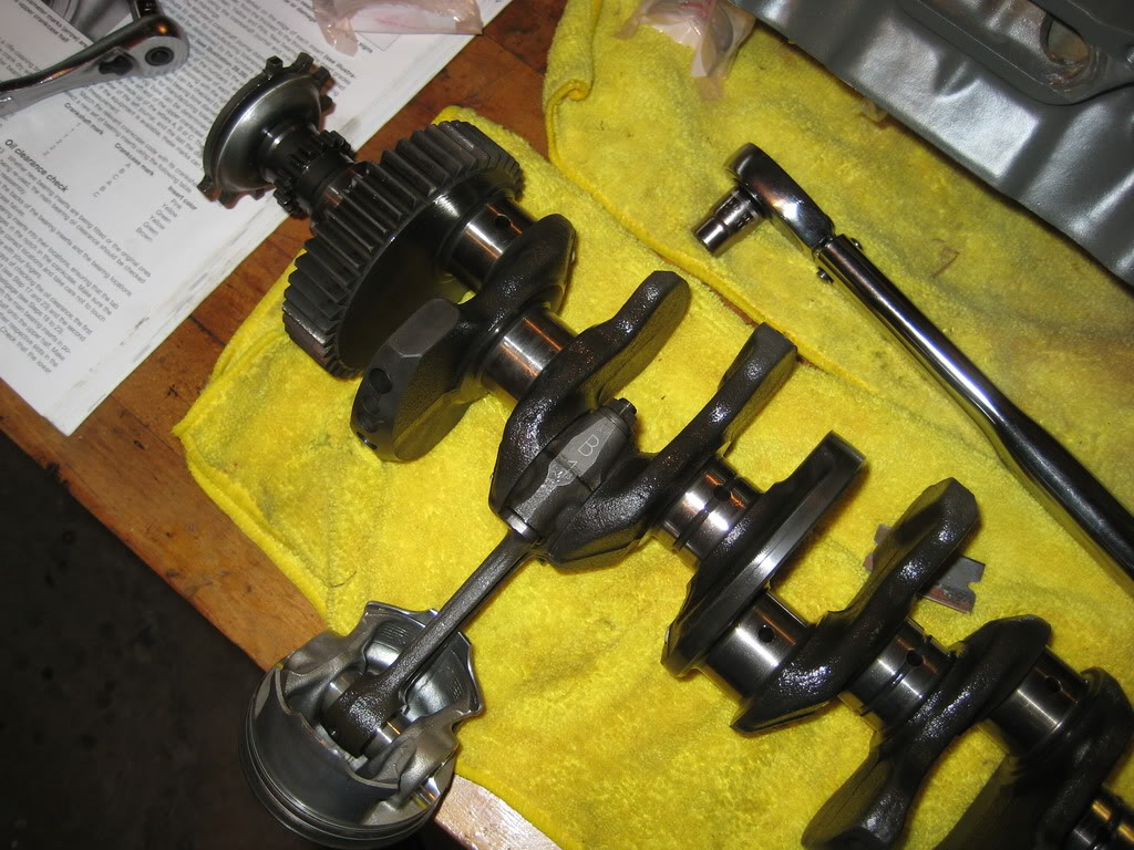
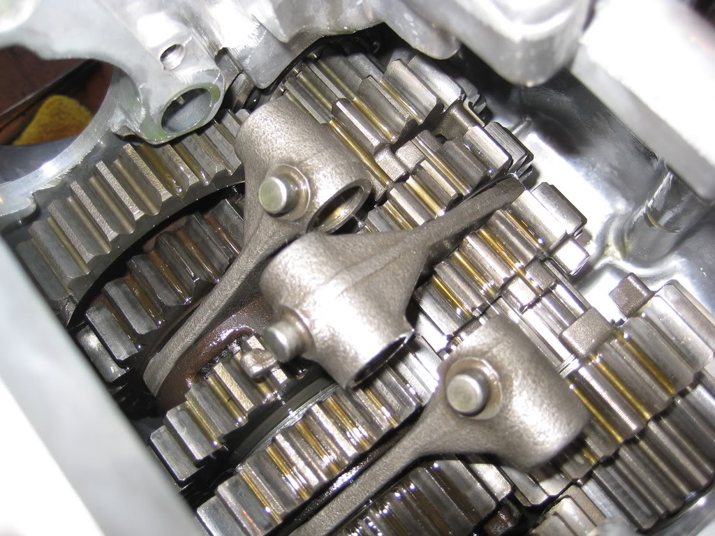
the first thing to go back in was the transmission. everything was cleaned up and gorgious.
then, because it is a pain to do it with the pistons installed, i checked all the connecting rod bearings with plastigauge to make sure that there was the proper oil clearance on the new bearings.
now.. the way to do that is this:
first... you figure out what size you need. then you buy it (i recommend using money for this, but... gold coins work as well)
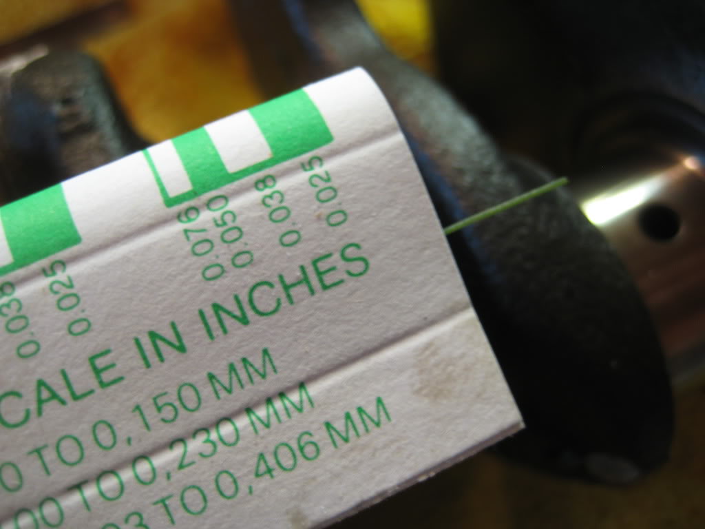
Then you cut a section roughly the width of the crankshaft journal corresponding to the connecting rod, and lay it across it.
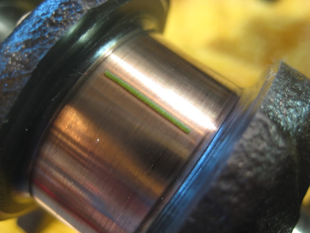
Then, install your connecting rod, and trying not to rotate it on the journal, torque the bolts down to the specified amount. For these it was 19 ft-lbs.
then carefully remove the connecting rod trying not to turn it. when you pull it off, you should see some smushed plastic; measure this with the gauge provided.
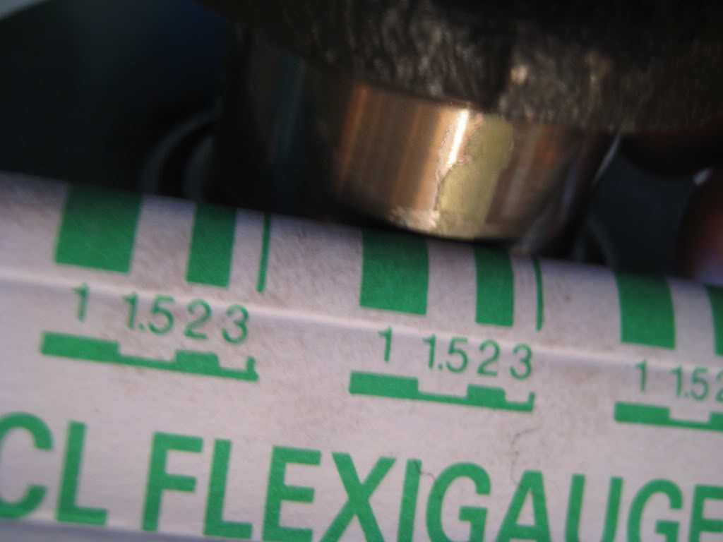
all my connecting rod bearings were right in the middle of spec, so i the proceeded to repeat the process with the crankshaft.
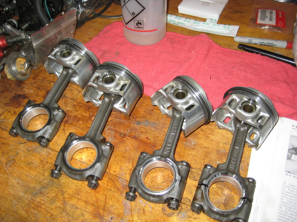
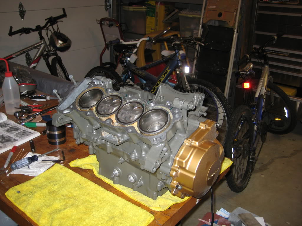
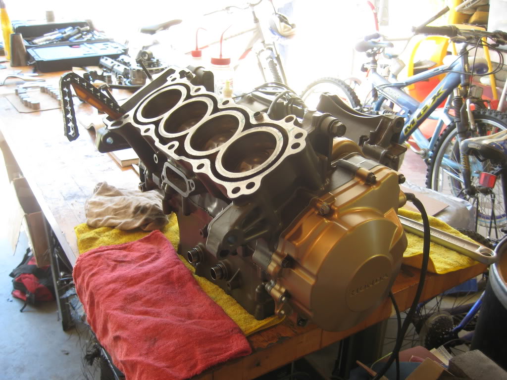
All the bearings were also in spec, so i proceeded to install the pistons.
here they are, all clean.

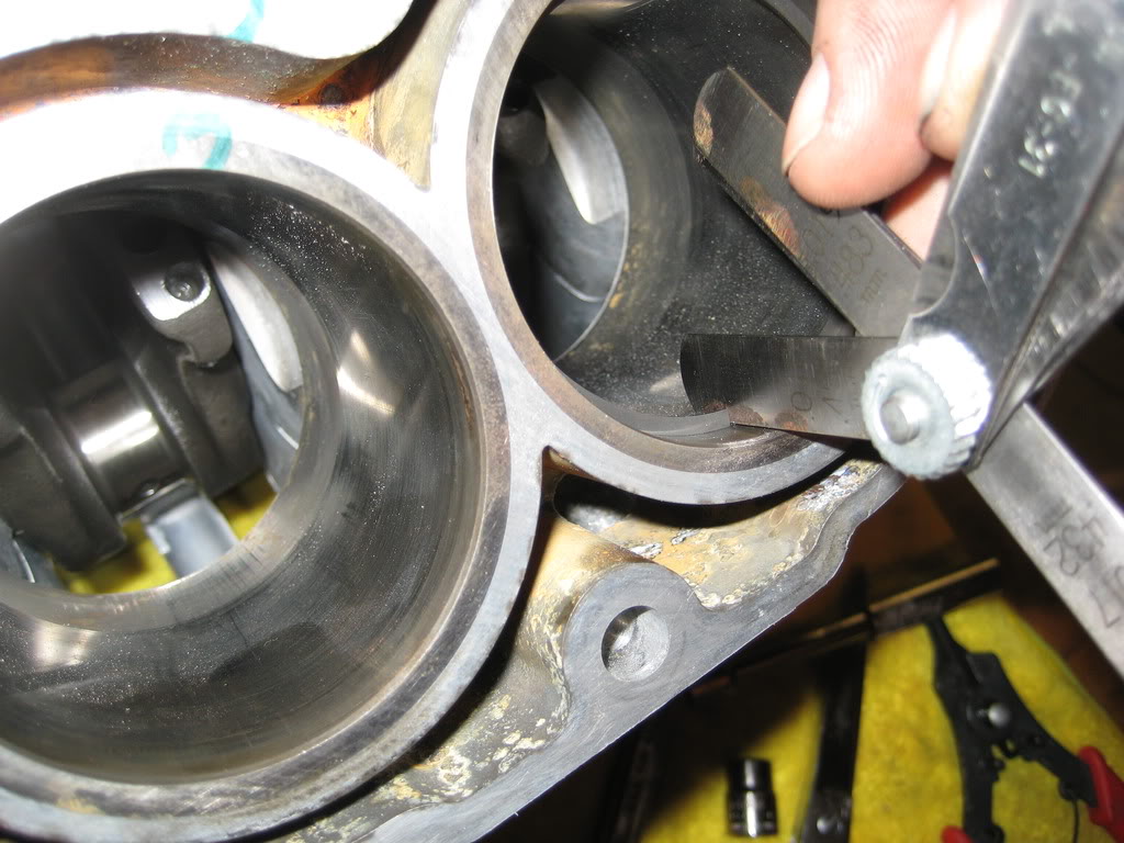
had to check the new rings for the proper end gap, which they all did
Installed the rings
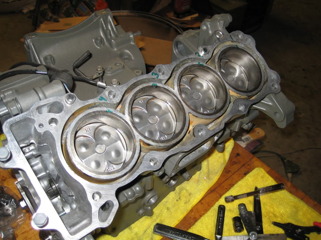
Installed the pistons
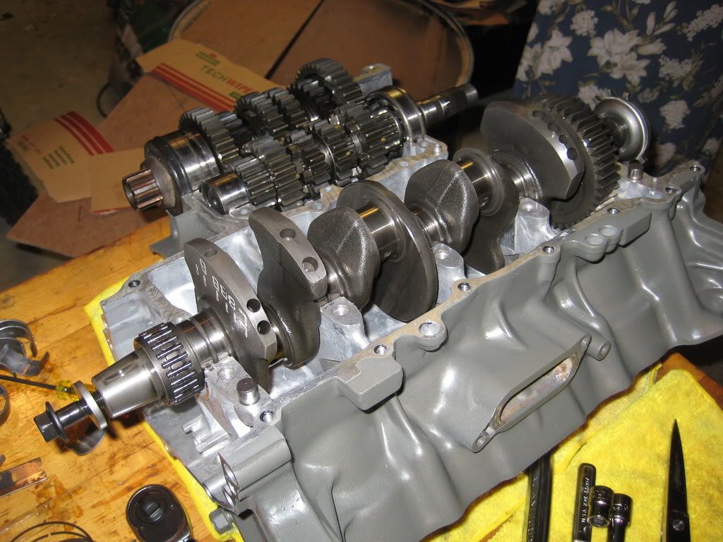
Then, i removed the crankshaft and cleaned all the bearing surfaces very thoroughly and made sure not to touch them with my bare fingers (this is a no-no apparently) and then liberally applied Lucas assembly lube to the bearings and journals (it helps to eliminate dry starts) then bolted the connecting rods to the crankshaft and torqued the bolts down.
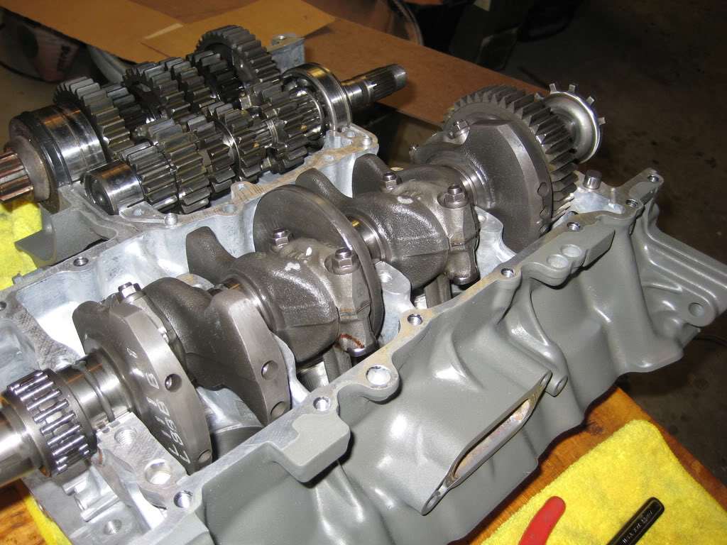
Now that the pistons were in it was time to put the crankcases back together. I applied Ultra Black (which is actually gray) gasket maker to the correct areas of the crankcases made sure everything lined up, and put that sucker together. I dont have any pictures of the sealant as i had to work quickly. I then bolted the case halves together in the specified order.
Here you have the cases back together, and with the alternator cover on for show
More to come! the hard part is done.
then, because it is a pain to do it with the pistons installed, i checked all the connecting rod bearings with plastigauge to make sure that there was the proper oil clearance on the new bearings.
now.. the way to do that is this:
first... you figure out what size you need. then you buy it (i recommend using money for this, but... gold coins work as well)
Then you cut a section roughly the width of the crankshaft journal corresponding to the connecting rod, and lay it across it.
Then, install your connecting rod, and trying not to rotate it on the journal, torque the bolts down to the specified amount. For these it was 19 ft-lbs.
then carefully remove the connecting rod trying not to turn it. when you pull it off, you should see some smushed plastic; measure this with the gauge provided.
all my connecting rod bearings were right in the middle of spec, so i the proceeded to repeat the process with the crankshaft.
All the bearings were also in spec, so i proceeded to install the pistons.
here they are, all clean.
had to check the new rings for the proper end gap, which they all did
Installed the rings
Installed the pistons
Then, i removed the crankshaft and cleaned all the bearing surfaces very thoroughly and made sure not to touch them with my bare fingers (this is a no-no apparently) and then liberally applied Lucas assembly lube to the bearings and journals (it helps to eliminate dry starts) then bolted the connecting rods to the crankshaft and torqued the bolts down.
Now that the pistons were in it was time to put the crankcases back together. I applied Ultra Black (which is actually gray) gasket maker to the correct areas of the crankcases made sure everything lined up, and put that sucker together. I dont have any pictures of the sealant as i had to work quickly. I then bolted the case halves together in the specified order.
Here you have the cases back together, and with the alternator cover on for show
More to come! the hard part is done.
Thread Starter
|
July 2011 ROTM
Joined: May 2010
Posts: 223
Likes: 8
From: Hampton Roads, VA
and now i have an update...
I put in the transmission shift dogs first as the transmission shafts are in.
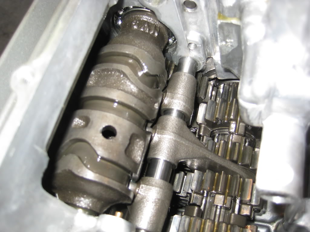
then put in the shift drum, alligning the tabs on the transmission forks.
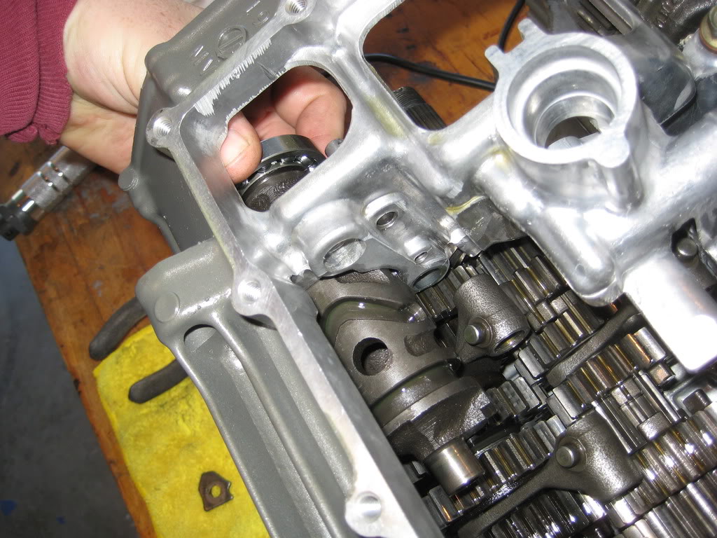
then slide the pin through the forks... and the transmission is done. all of this is with some Lucas assembly lube.
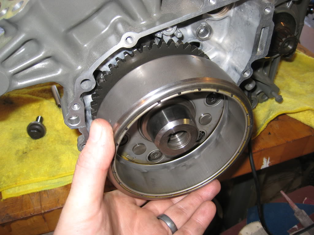
then put in the alternator rotor
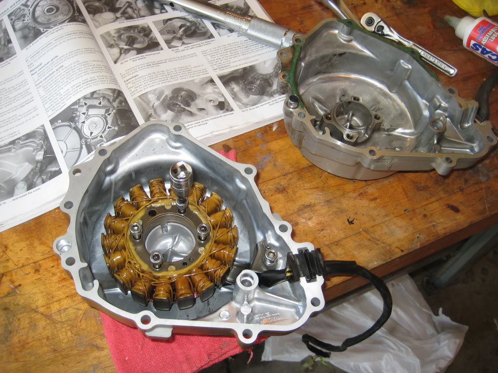
and transferred the coil to the new cover
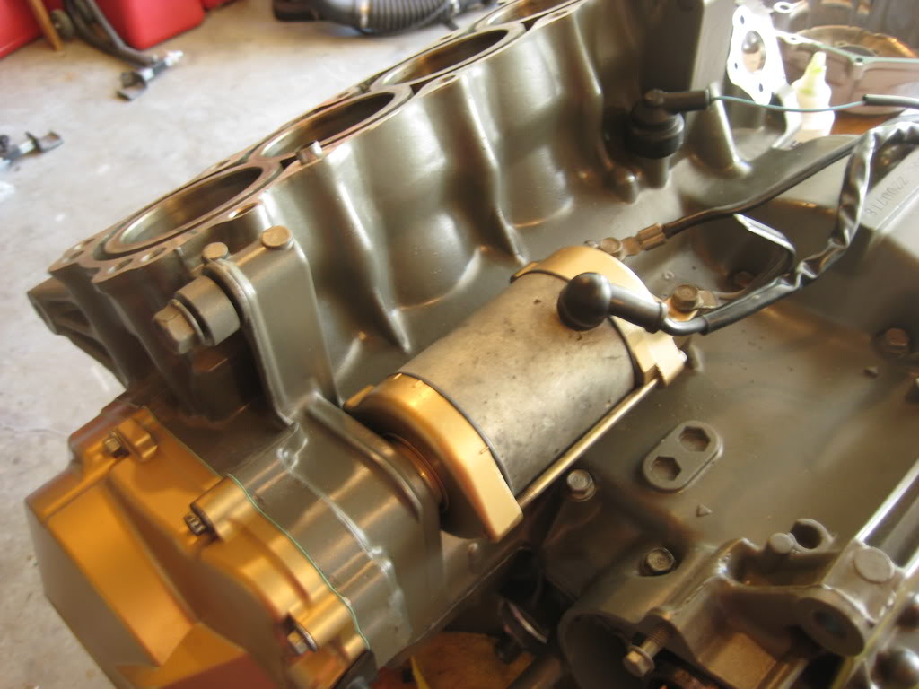
rebuilt the starter and added some bling
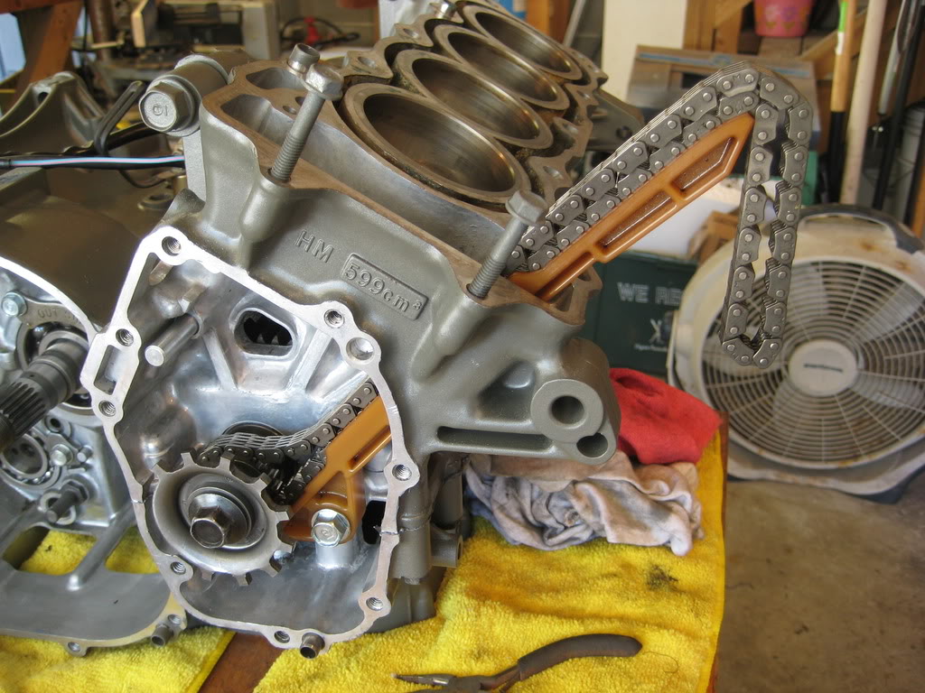
added the cam chain and rear guard
then i found out that the gear shift spindle was bent and had been badly repaired.
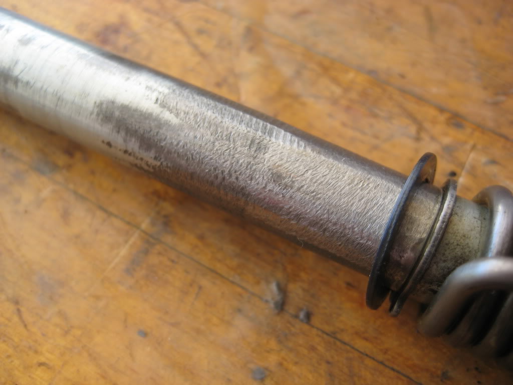
scored a new one on ebay for $7 just have to wait for it to arrive
cleaned and reassembled the oil pump
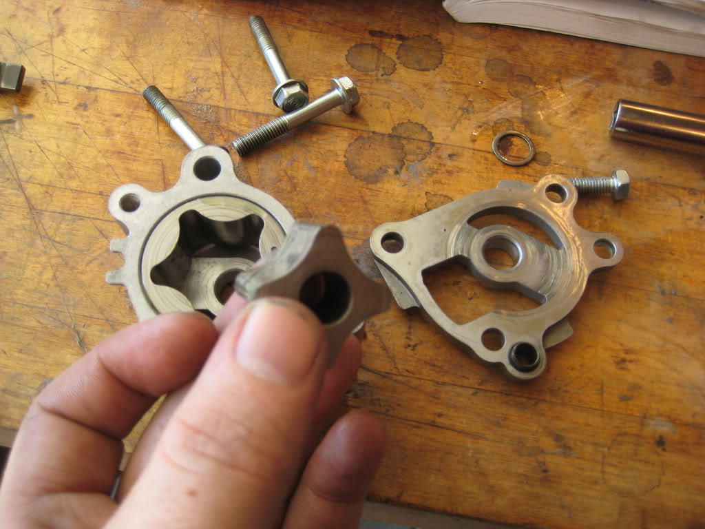
Installed...
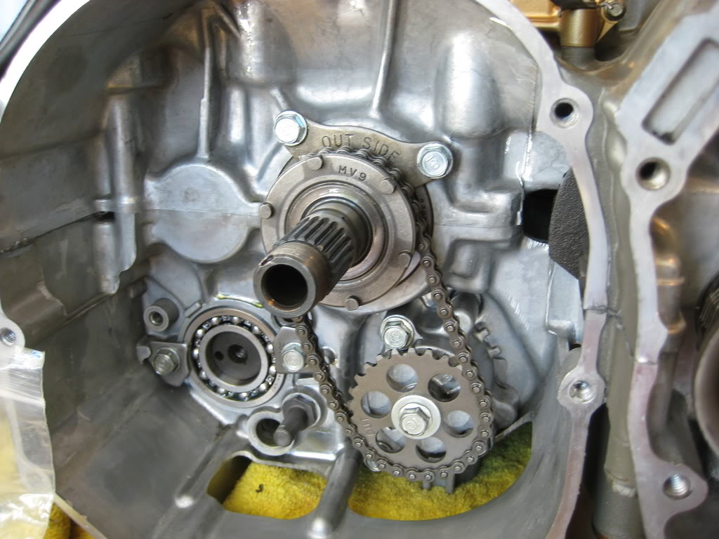
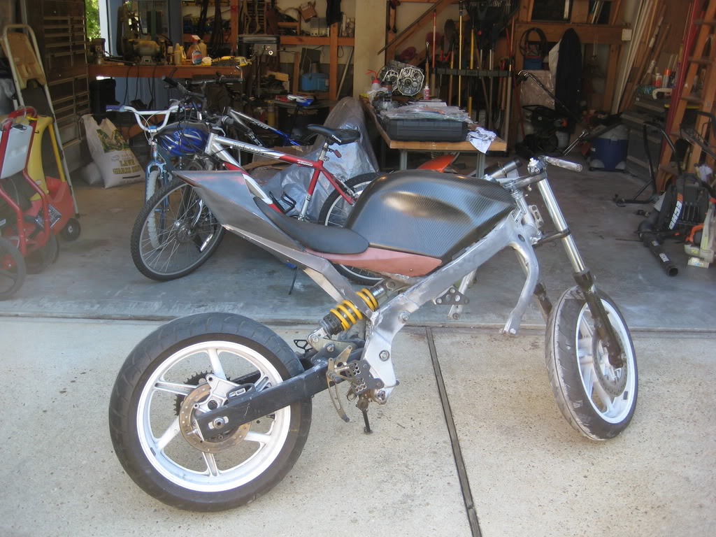
engine shot..
body shot...
okay... this sounds reallly funny, but what ties the crankshaft to the transmission?! i mean they dont connect in any way right now... what ties them together?
thanks so much for reading!
~Chris
I put in the transmission shift dogs first as the transmission shafts are in.
then put in the shift drum, alligning the tabs on the transmission forks.
then slide the pin through the forks... and the transmission is done. all of this is with some Lucas assembly lube.
then put in the alternator rotor
and transferred the coil to the new cover
rebuilt the starter and added some bling
added the cam chain and rear guard
then i found out that the gear shift spindle was bent and had been badly repaired.
scored a new one on ebay for $7 just have to wait for it to arrive
cleaned and reassembled the oil pump
Installed...
engine shot..
body shot...
okay... this sounds reallly funny, but what ties the crankshaft to the transmission?! i mean they dont connect in any way right now... what ties them together?
thanks so much for reading!
~Chris
Senior Member
Joined: May 2010
Posts: 1,753
Likes: 3
From: West Monroe,Louisiana
The big gear that goes behind the clutch assembly.
*edit* - thanks for all of the pictures - that's one of the best pics of the transmission I've seen, and I'll need it this winter when I try to see if I need to replace my 2nd gear.
*edit* - thanks for all of the pictures - that's one of the best pics of the transmission I've seen, and I'll need it this winter when I try to see if I need to replace my 2nd gear.

Thread Starter
|
July 2011 ROTM
Joined: May 2010
Posts: 223
Likes: 8
From: Hampton Roads, VA
If i can get any picture you need before getting into your motor while i have mine open just let me know.
thanks for reading!
~chris
Thread Starter
|
July 2011 ROTM
Joined: May 2010
Posts: 223
Likes: 8
From: Hampton Roads, VA
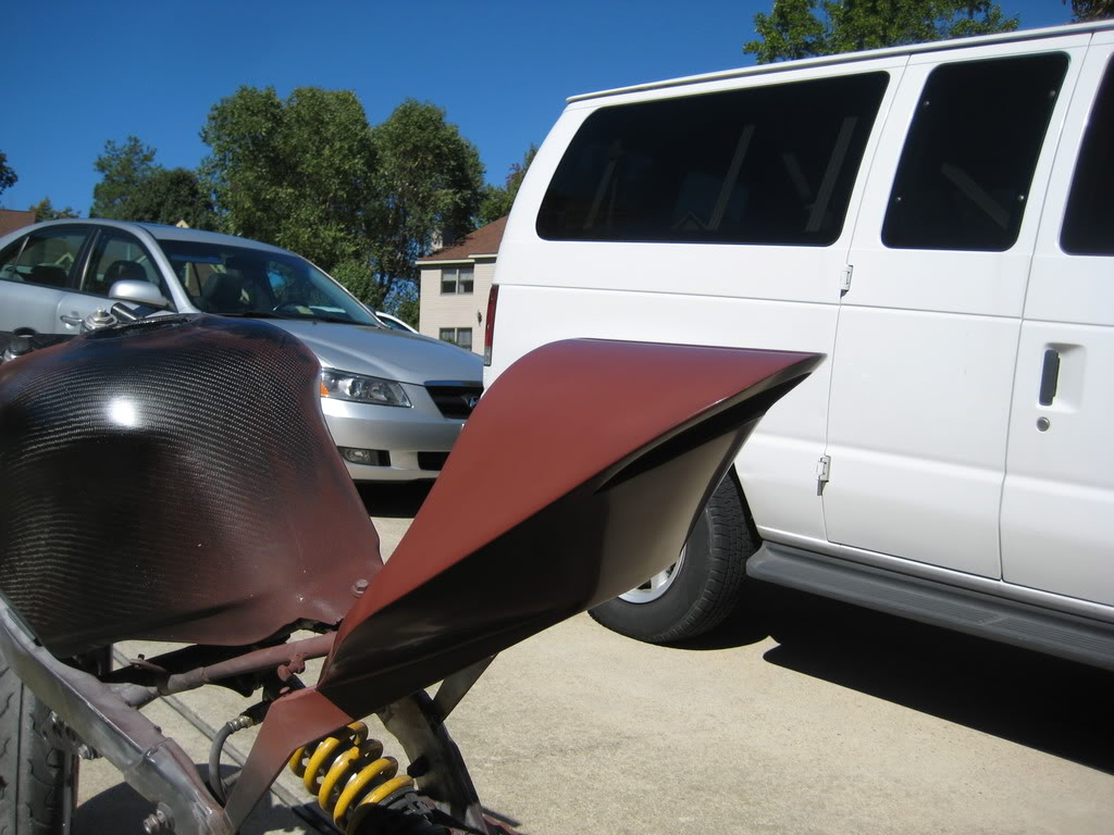
thats a great idea. i do think that some of the edges need a bit of rounding to match the styling of the tank... so i am gonna incorporate that in, however, i do like the idea of getting it photochopped.
now... i have an update.
I did a good bit over the long weekend, and i will prolly take two posts.
I got to work, and started by sanding and polishing the tail in prep for laying the mold.
Then made a template for the splitter-plate
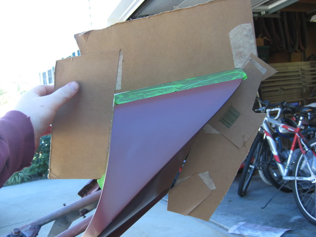
Transferred that onto Masonite
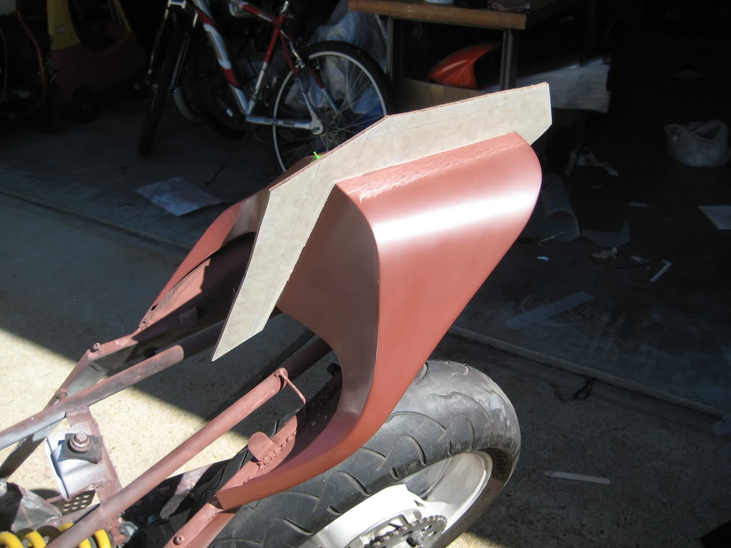
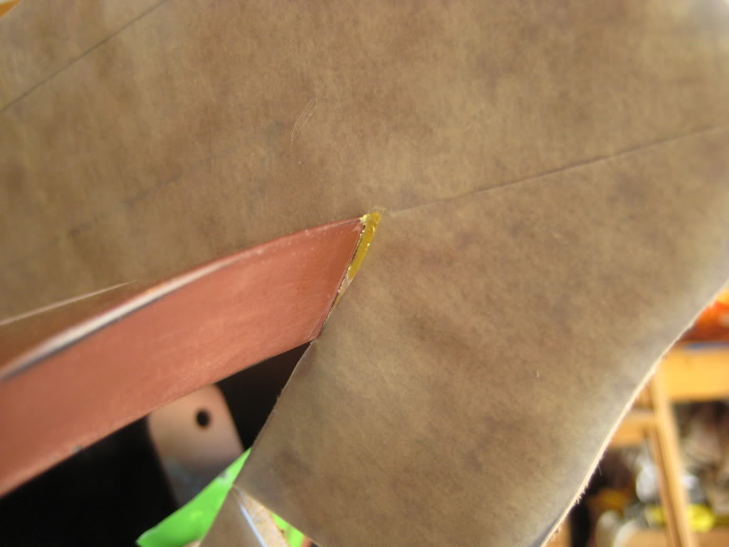
I used bondo to hold it on the tail.
The used clay to fill in any gaps the bondo left.
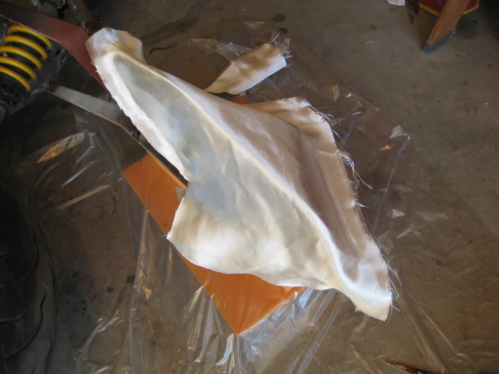
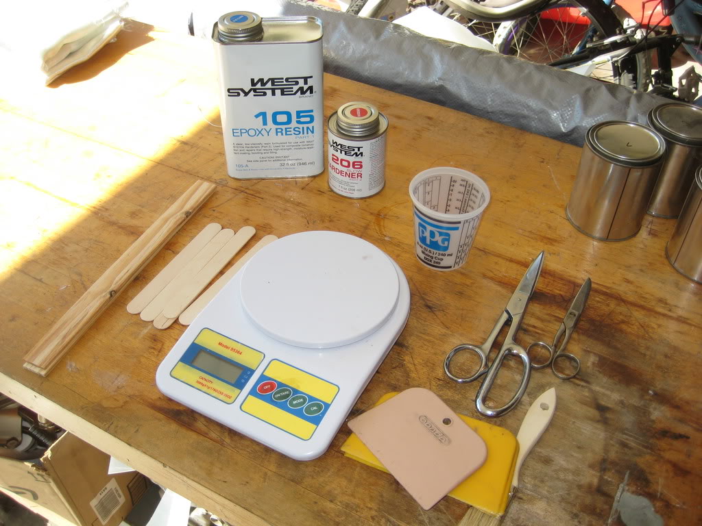
Figured out what shape of cloth i needed then cut out all my layers. One layer of very light glass, three medium weight and one heavy layer.
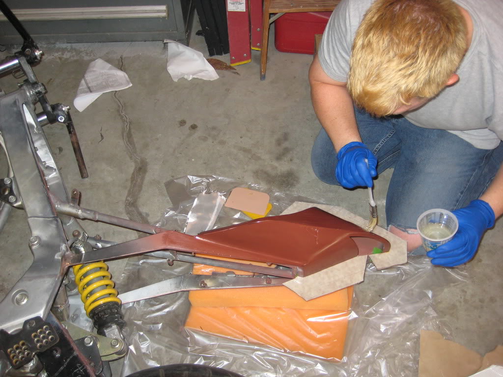
I got everything ready, and then l brushed on the first layer of resin
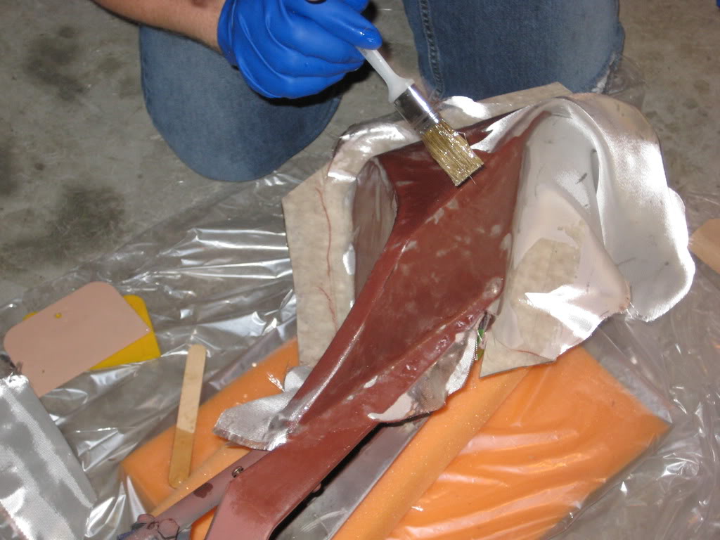
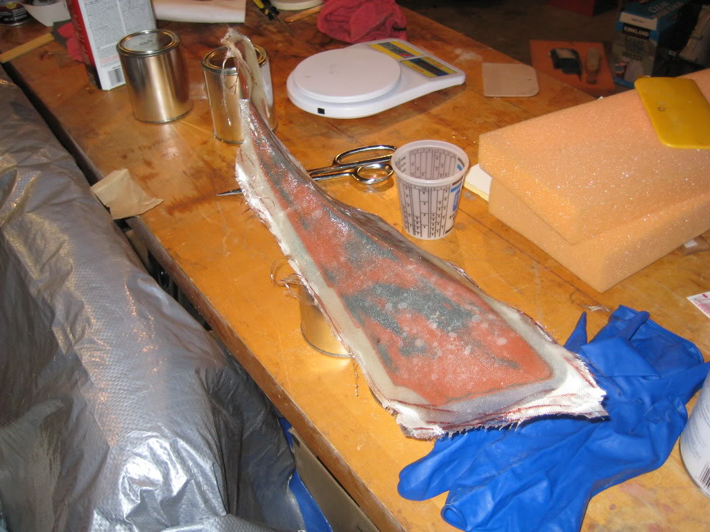
the first layer of glass going on... the light glass cloth is very flexible and transparent making it easy to spot defects, and usually leaves fewer flaws.
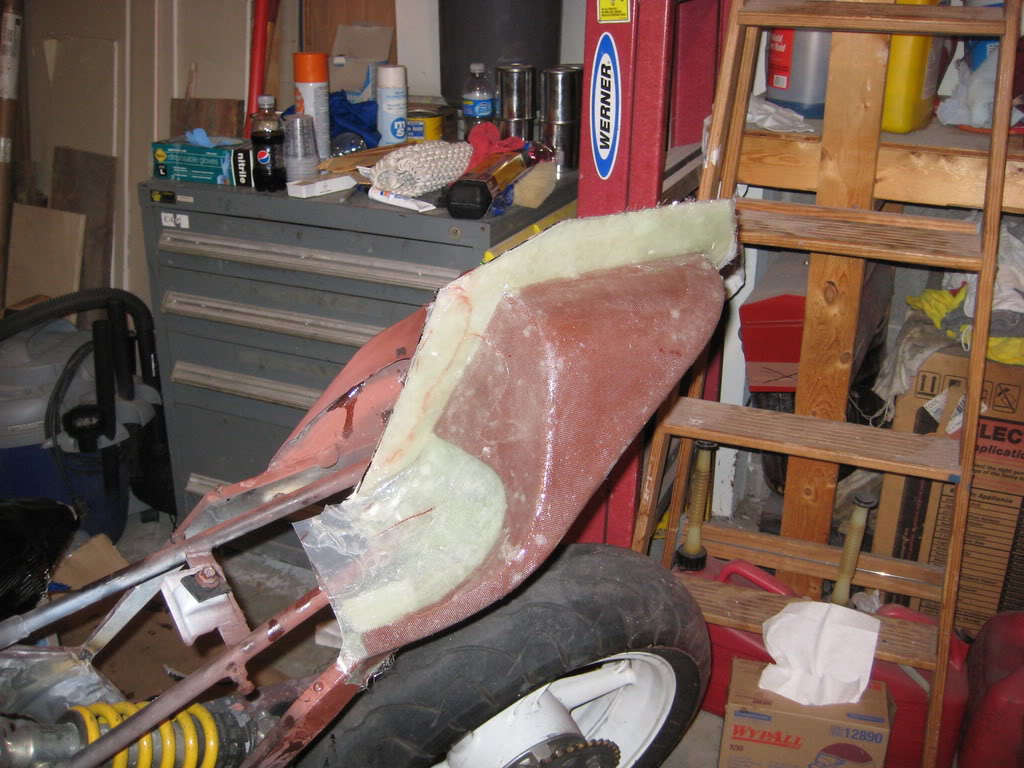
And... all 5 layers on and dry
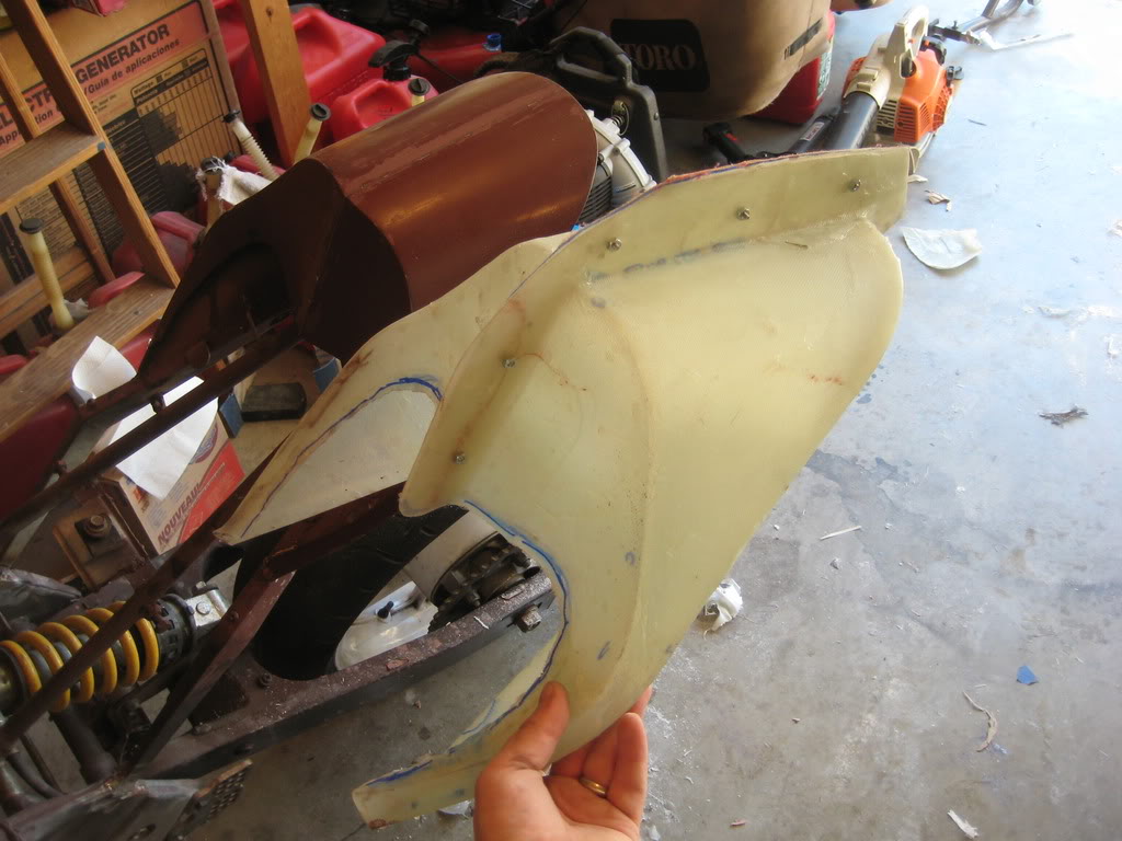
Splitter plate removed and ready for the second part. I wax and release the whole thing, the fiberglass flange too.
Side two layed up
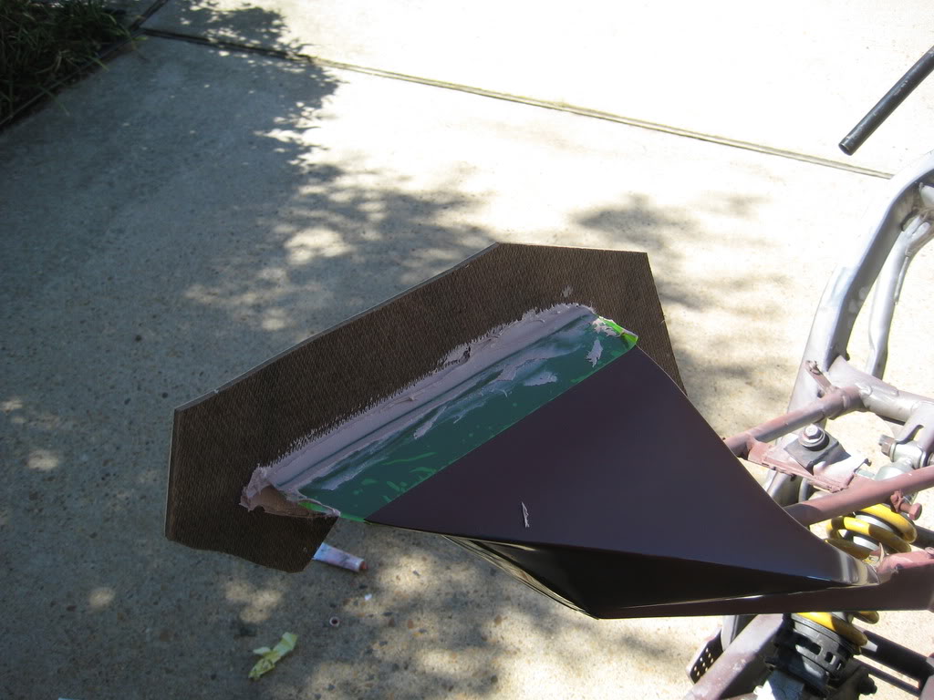
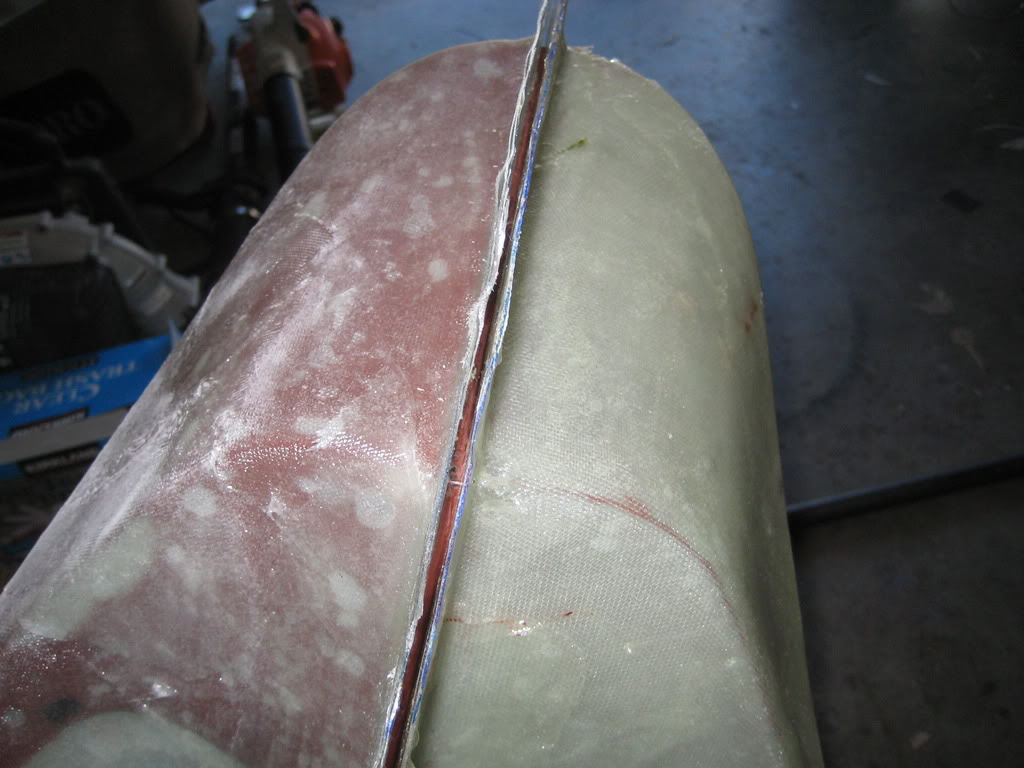
Now i am trying to get the parts off, you can see here that the whole part is still stuck to the tail except fro right at the split where i have been prying at it.
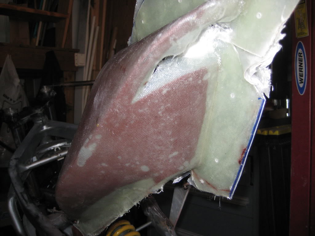
Now after working at it, you can see how the whole part has separated from the tail.
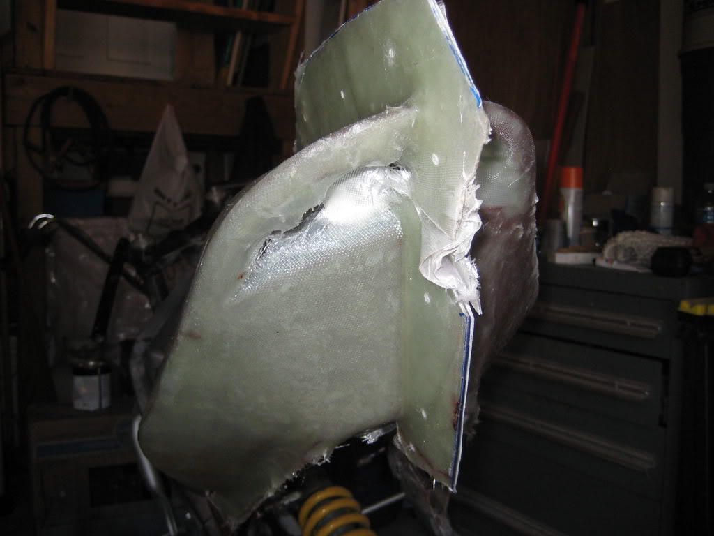
Side one off
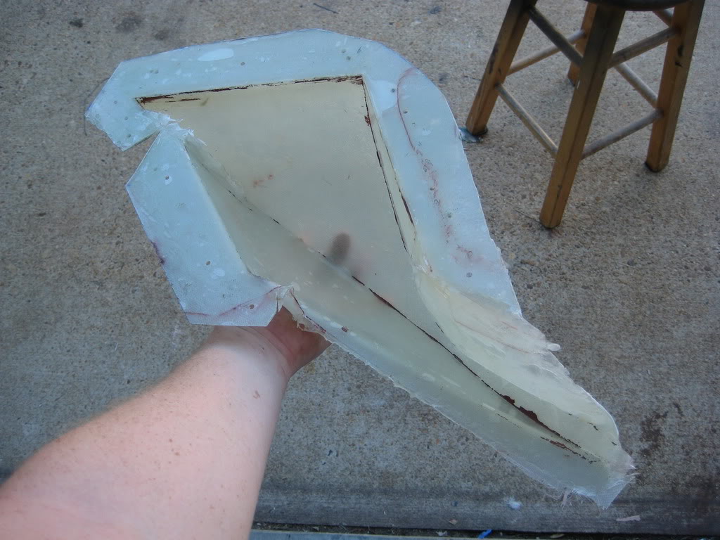
Both parts off and bolted together. (the wholes were drilled while it was still on the tail
And here you can see i have started working on adding some radii to the part so it will match the tank a little more.
thanks for watching...
more to come soon
Thread Starter
|
July 2011 ROTM
Joined: May 2010
Posts: 223
Likes: 8
From: Hampton Roads, VA
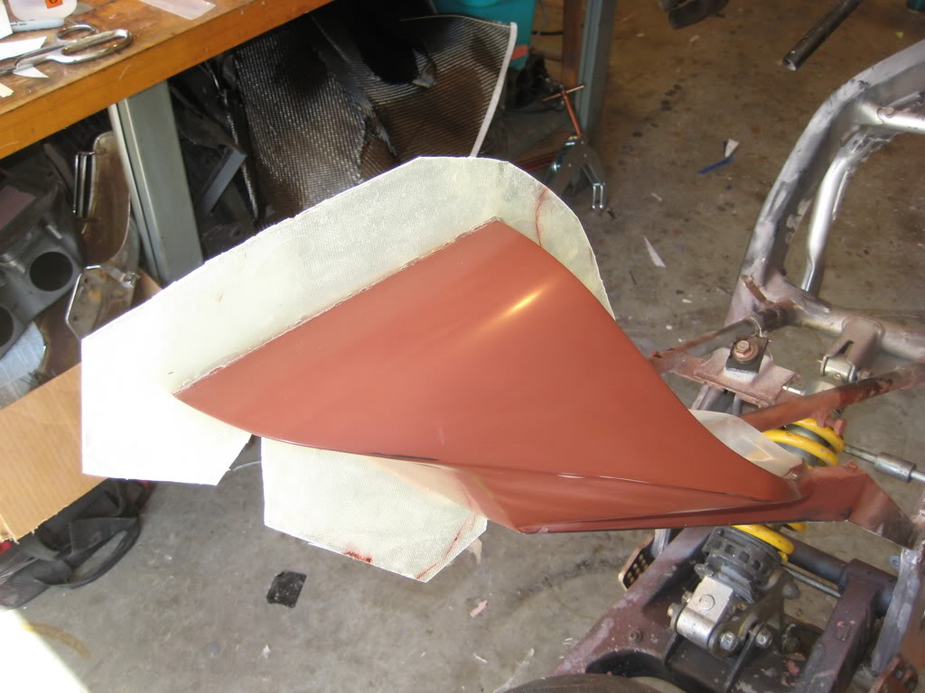
I also worked on the side-covers.
I got the parts ready and did the final body work before spraying them with primer, sanding and polishing them

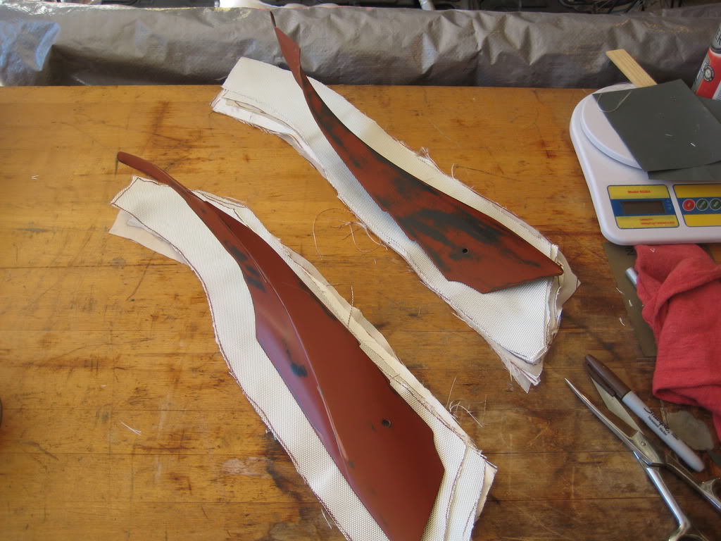
Figured out what the cloth needed to look like
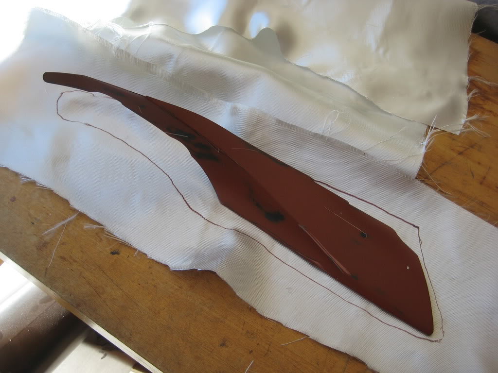
then cut out all the layers, ready to lay up
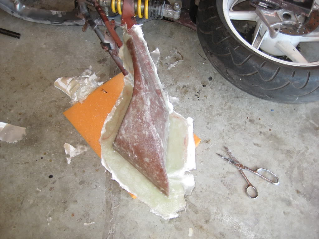
Got everything set-up and ready
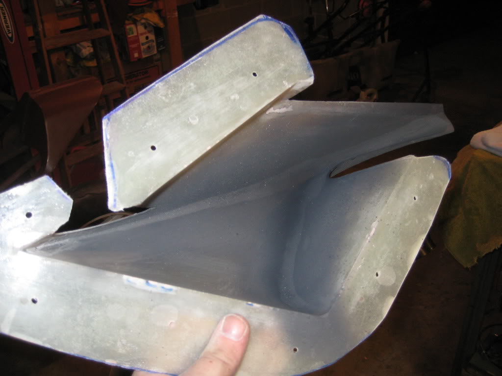
Here is one side laid up and curing
And the mold removed... still needs a little clean-up
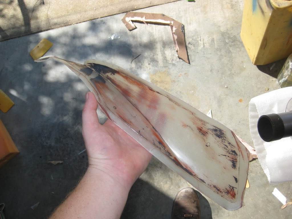
now i am just getting all the molds ready to make real carbon parts.
that is next...
thanks for looking
~Chris
I got the parts ready and did the final body work before spraying them with primer, sanding and polishing them
Figured out what the cloth needed to look like
then cut out all the layers, ready to lay up
Got everything set-up and ready
Here is one side laid up and curing
And the mold removed... still needs a little clean-up
now i am just getting all the molds ready to make real carbon parts.
that is next...
thanks for looking
~Chris

