Blade FZR Union
#31
Wiring Update:
After a good bit of puzzling over the loom diagrams I’ve shed a load of excess from the Loom….
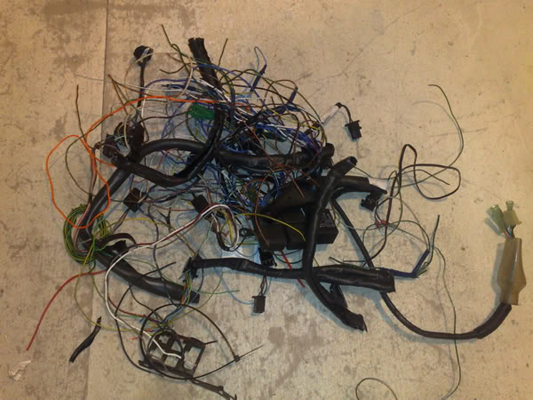
I hate wiring………
Look at the state of all this..
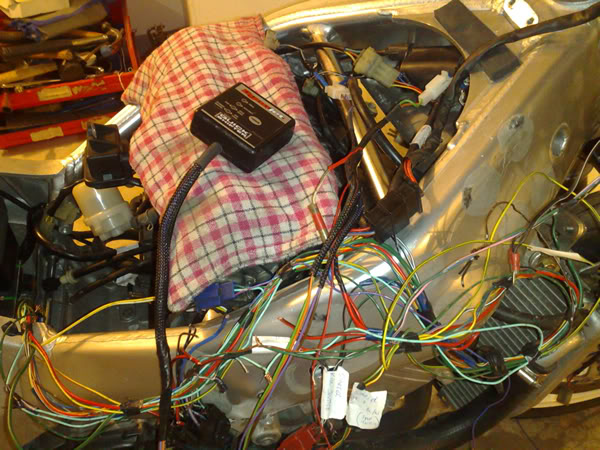
Lost a load from the Quickshift Loom too tho ……..

Just look how much there is to deal with up this end !!

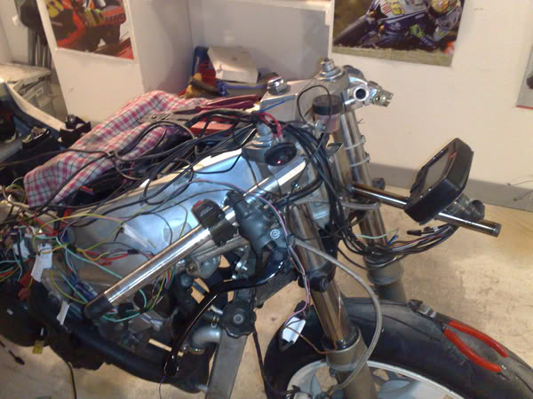
Did I mention I don’t like wiring…..?
Anyhow I needed to finish the mounting of the Ignitor and Rec/reg and put the Quickshift control box somewhere. I had thought I’d put it underneath the tail unit but not sure just how exposed it’ll be and how much crud will get all over it…. After extending the Reg/Rec wires and routing the ignitor wires around the side of my new bracket this is what it looks like here….
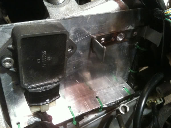
They run under the bottom fold and I’ve notched a hole for the connecter to the reg/rec unit. I know those cable ties look nasty in green but when its been run and had a proper shake down I’ll tear it all down again and get the frame powder coated and the plastics painted, till then its all functional only.
I’ve put Velcro on the front of the ignitor box ..
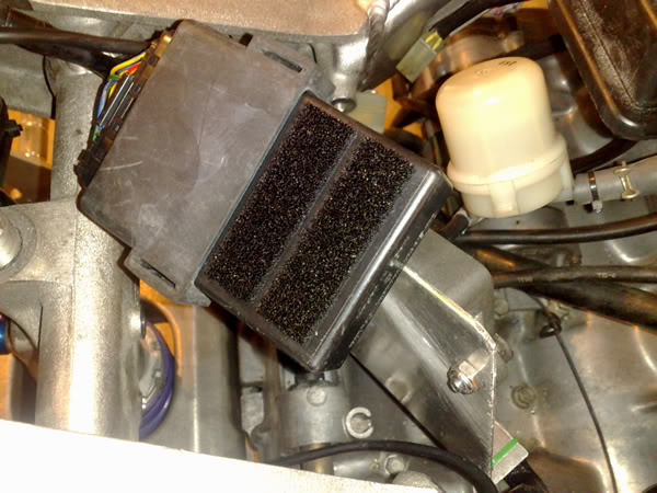
here is the bracket in its position …..
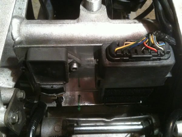
The Quickshift controller………….
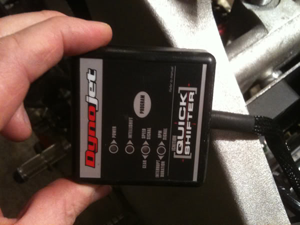
And the Velcro on the back ….
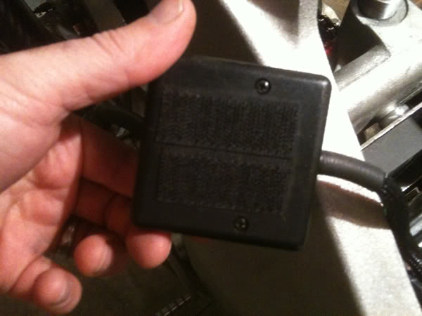
And its final resting place …………
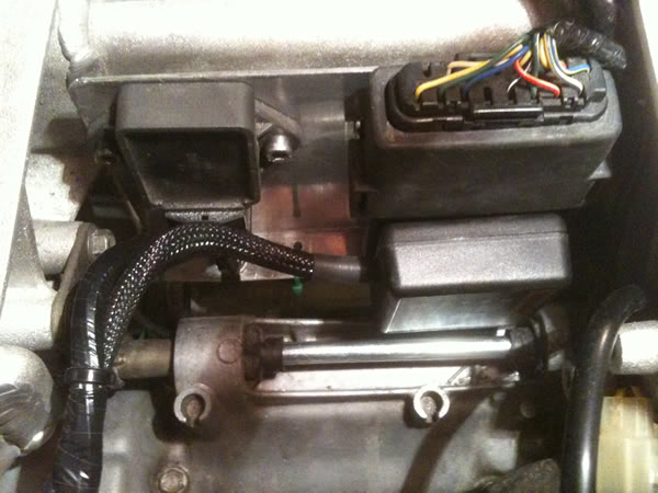
Also from above ….
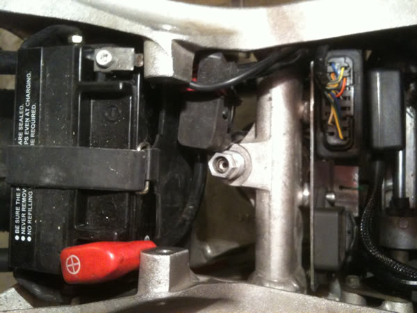
Enough slack to remove and setup ….

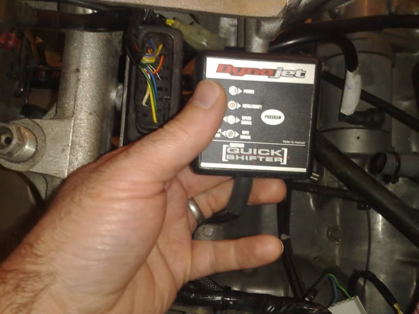
Happy Days
After a good bit of puzzling over the loom diagrams I’ve shed a load of excess from the Loom….

I hate wiring………
Look at the state of all this..

Lost a load from the Quickshift Loom too tho ……..


Just look how much there is to deal with up this end !!

Did I mention I don’t like wiring…..?

Anyhow I needed to finish the mounting of the Ignitor and Rec/reg and put the Quickshift control box somewhere. I had thought I’d put it underneath the tail unit but not sure just how exposed it’ll be and how much crud will get all over it…. After extending the Reg/Rec wires and routing the ignitor wires around the side of my new bracket this is what it looks like here….

They run under the bottom fold and I’ve notched a hole for the connecter to the reg/rec unit. I know those cable ties look nasty in green but when its been run and had a proper shake down I’ll tear it all down again and get the frame powder coated and the plastics painted, till then its all functional only.
I’ve put Velcro on the front of the ignitor box ..

here is the bracket in its position …..

The Quickshift controller………….

And the Velcro on the back ….

And its final resting place …………

Also from above ….

Enough slack to remove and setup ….

Happy Days
#32
Just thought I’d add this little bit as it might be of interest to a few, If like me you’ve dreaded doing any wiring then stumbling over this kit was a real breath of fresh air. For me changing the wiring length and putting connecters on wires always consisted of those nasty crimped bullet types which pulled off and came in a grand choice of red or blue. This kit I found was very reasonable and I even got a proper pair of pliers too.
So first the collection of new wires…
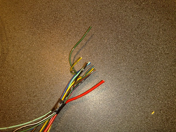
Then the insulation stripping
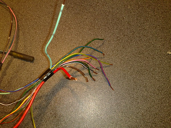
These connecters came with all the spade and female parts ready…


The only fiddly bit was holding the end while you offer up the pliers…

Once crimped they’re really tight … I put a little solder on the end too to be sure but I doubt its needed..
All ready for the block …
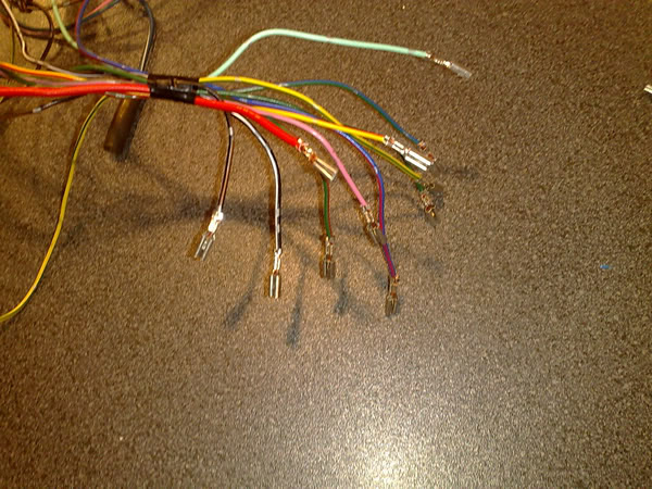
Just push and click ....... Shimples…..
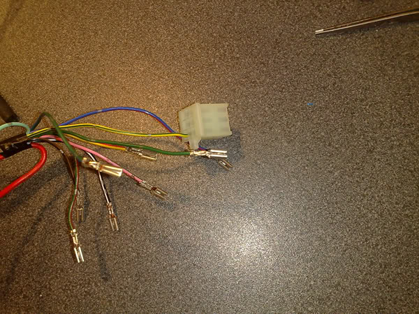
So first the collection of new wires…

Then the insulation stripping

These connecters came with all the spade and female parts ready…


The only fiddly bit was holding the end while you offer up the pliers…

Once crimped they’re really tight … I put a little solder on the end too to be sure but I doubt its needed..
All ready for the block …

Just push and click ....... Shimples…..

#33
Those based in the UK here's a link for the wiring supplies.....
http://www.vehicle-wiring-products.e...e/homepage.php

http://www.vehicle-wiring-products.e...e/homepage.php
#34
Evening all this week has been filled with the joys of wiring and as we’ve moved further up the bike and toward the front the time had come to decide on the coils. I guess they were really only going to fit somewhere by the headstock where the FZR ones were so I just had a play around with how the mounting would be done to maximize the limited space there was.
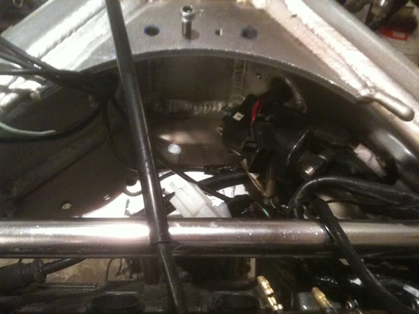
I’ve just used some SS tube to sit the coil off the inside face of the frame rail and when I finished I also ran an extra earth wire to be sure I had a good ground for both the coils in position. Apologies for the quality of pictures I’ll try to get some better ones at some point and replace these. Here’s the LHS coil.
I ran an additional earth wire linking the two coils to get a good grounding. I also drilled and tapped the holes for a blind fix onto the frame.
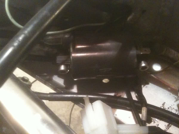
The right hand coil which feeds Cyl 1+4 is very close to the No 4 pot so I trimmed a good chunk of the HT lead off helping to keep things a little less messy.
After finishing all the connecter blocks and making sure they weren’t too many wires blocked together so that they can be disconnected and drawn through the frame holes, I moved on with my cover...
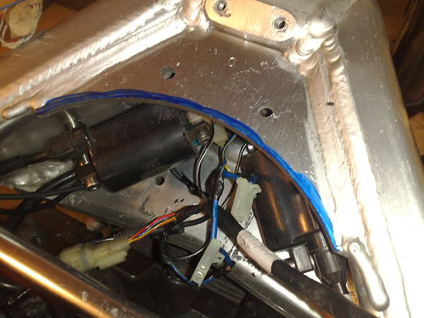
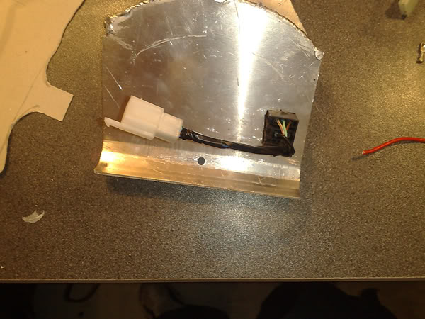
Ok the cover has a few purposes one of which I’ll go into later but I want to cover all this (There is a lot more wiring especially the logging stuff) and just have access to a few vital things. It has to be light of course … here I’ve cleaned the area and using a marker I’m going to take a guide for the shape.

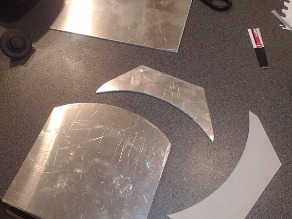
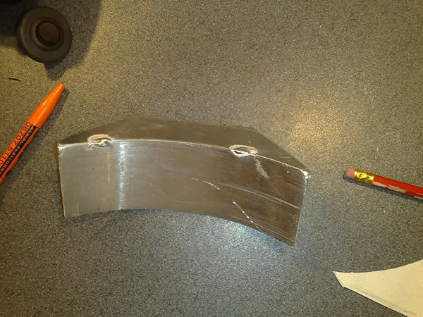
I’ve used a set of rollers to curve this which I picked up cheap from a local college… I know I said I wanted to use the minimum stuff you’d have in a regular garage but it’s something I’ve been after for a while and I’d like to do a lot more fabrication in the future so it made sense.
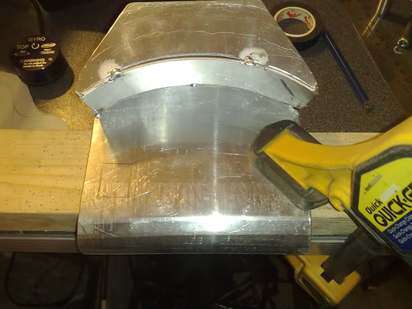
This seemed to take ages as although it’s difficult to see from this angle the flat portion of this cover plate where the clamp is had to be as horizontal to the ground as possible when mounted and the bike sat in its riding position with me onboard. More about this later……………..
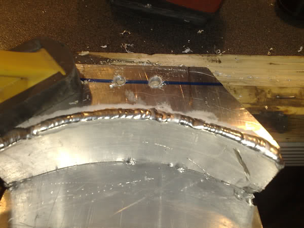
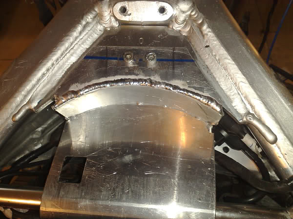
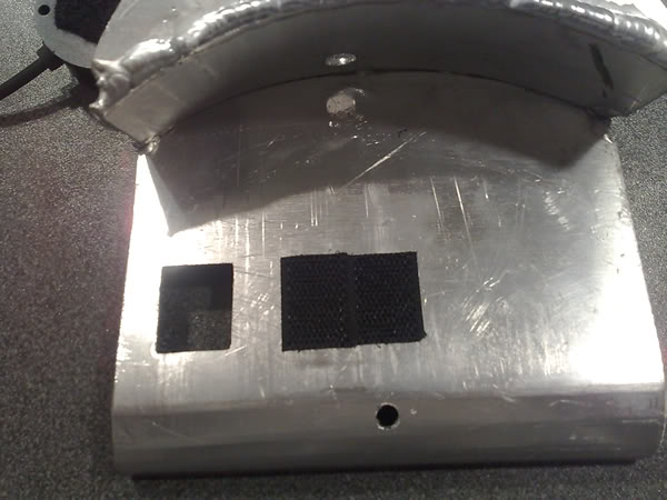
That’s Velcro and not another hole……….see?
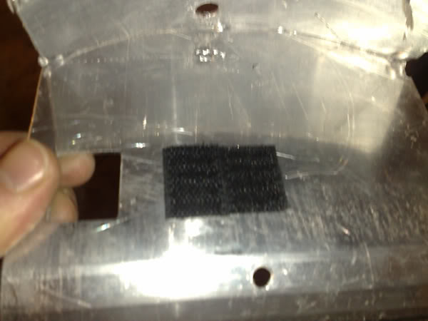
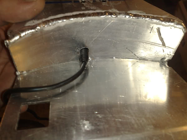
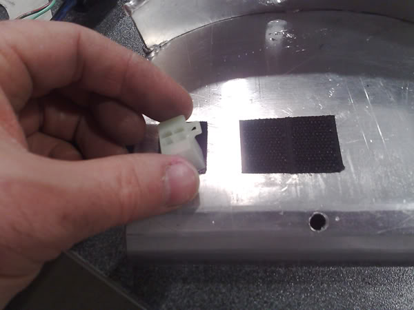
Making sure my connecter will fit ok…….
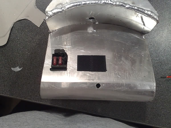
So this is where the ignition fuse will live with a spare and the clutch diode…. The bike refused to run without it? Still can’t figure that out as id tried to bypass it ??? Anyone know why?
That’s it for that ……………….

I’ve just used some SS tube to sit the coil off the inside face of the frame rail and when I finished I also ran an extra earth wire to be sure I had a good ground for both the coils in position. Apologies for the quality of pictures I’ll try to get some better ones at some point and replace these. Here’s the LHS coil.
I ran an additional earth wire linking the two coils to get a good grounding. I also drilled and tapped the holes for a blind fix onto the frame.

The right hand coil which feeds Cyl 1+4 is very close to the No 4 pot so I trimmed a good chunk of the HT lead off helping to keep things a little less messy.
After finishing all the connecter blocks and making sure they weren’t too many wires blocked together so that they can be disconnected and drawn through the frame holes, I moved on with my cover...

Ok the cover has a few purposes one of which I’ll go into later but I want to cover all this (There is a lot more wiring especially the logging stuff) and just have access to a few vital things. It has to be light of course … here I’ve cleaned the area and using a marker I’m going to take a guide for the shape.


I’ve used a set of rollers to curve this which I picked up cheap from a local college… I know I said I wanted to use the minimum stuff you’d have in a regular garage but it’s something I’ve been after for a while and I’d like to do a lot more fabrication in the future so it made sense.

This seemed to take ages as although it’s difficult to see from this angle the flat portion of this cover plate where the clamp is had to be as horizontal to the ground as possible when mounted and the bike sat in its riding position with me onboard. More about this later……………..


That’s Velcro and not another hole……….see?

Making sure my connecter will fit ok…….


So this is where the ignition fuse will live with a spare and the clutch diode…. The bike refused to run without it? Still can’t figure that out as id tried to bypass it ??? Anyone know why?

That’s it for that ……………….
#36
Now then … as the wiring comes to an end I’ve been looking at a few other issues that need addressing pretty soon. The front sprocket position as I’d mentioned before was approximately 10mm too far out.
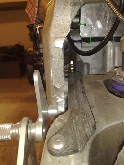
As I’d nowhere to bring the motor over I turned my attention to the output shaft. Looking at it was fairly promising ….. the bush behind the sprocket that sits into the seal looks to have plently of meat on it and the plan was to remove the excess here…….unfortunately when I went down to the engineers to pick it up there was a problem …
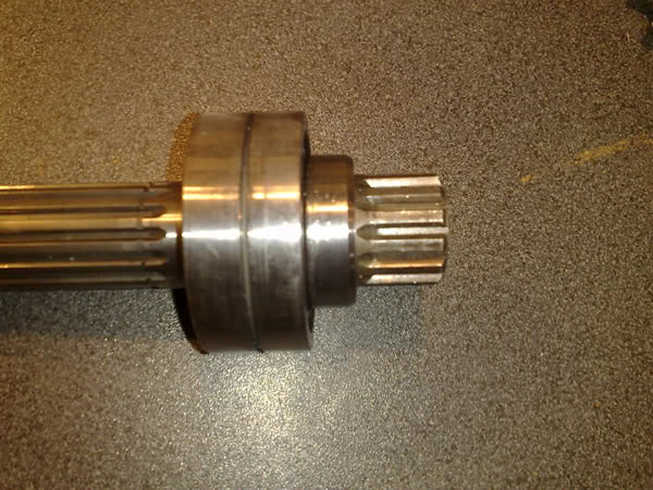
Having the bushed machined down just exposed the taper on the shaft so the sprocket wouldn’t slide back enough. So it came down to the sprocket too which I thought might give me as much as 5mm as you can see with the original next to the new machined one ………..
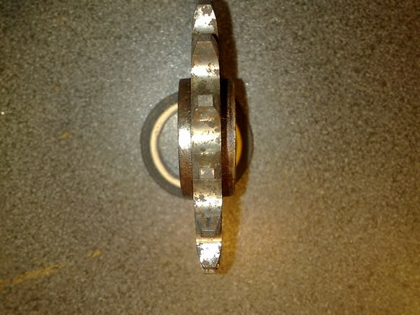
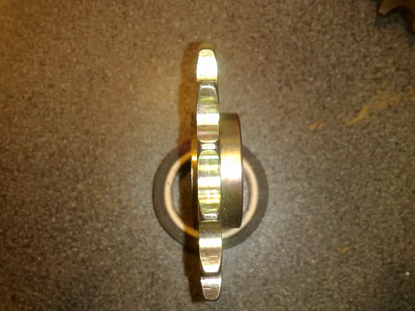
All that was left to do was taper out the inside face to slide nicely over the tapered shaft. The outside was left untouched to keep the load spread and remain strong enough for the job.
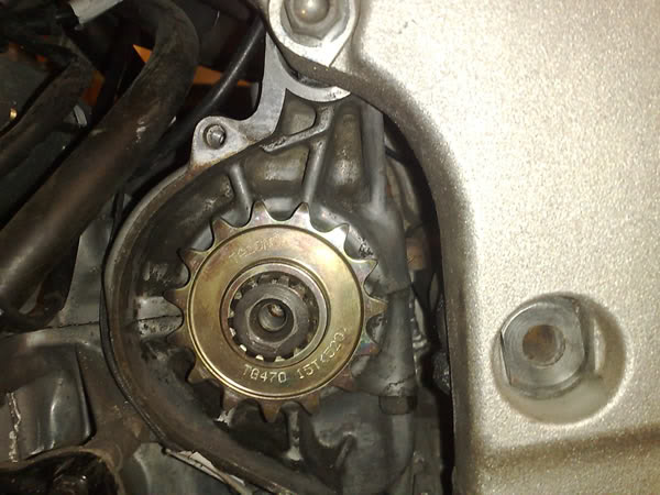
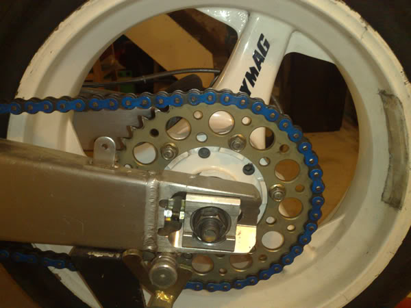
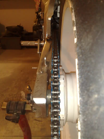
Straight as a middle wicket!
Eagle eyes will spot the 520 lightweight conversion… Lovely Jubbly!


As I’d nowhere to bring the motor over I turned my attention to the output shaft. Looking at it was fairly promising ….. the bush behind the sprocket that sits into the seal looks to have plently of meat on it and the plan was to remove the excess here…….unfortunately when I went down to the engineers to pick it up there was a problem …

Having the bushed machined down just exposed the taper on the shaft so the sprocket wouldn’t slide back enough. So it came down to the sprocket too which I thought might give me as much as 5mm as you can see with the original next to the new machined one ………..


All that was left to do was taper out the inside face to slide nicely over the tapered shaft. The outside was left untouched to keep the load spread and remain strong enough for the job.


Straight as a middle wicket!
Eagle eyes will spot the 520 lightweight conversion… Lovely Jubbly!
#37
#39
#40


