
Blade FZR Union
#21
 04-23-2010, 05:52 PM


Join Date: Feb 2010
Location: LANCS UK
Posts: 76
Likes: 0
Received 0 Likes
on
0 Posts
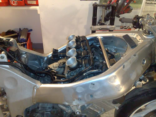
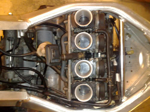
Hey all �. The project is at one of those funny stages with still a lot to do but also some hope that the end could come eventually. This week I�ve done brackets for the radiator, mounted the carbs and essentially plugged in all the electrics to see if it�ll fire up. The carbs are sooo tight that the TPS had to be removed just to get them on. Look at the picture�. Theres really no room for anything else! I�ll have to at some point, figure out an airbox of sorts and see if the tank will fit properly. I might even need a fuel pump as the carbs are high in relation to the bottom of where the tank will sit.
#22
04-25-2010, 01:27 PM
Join Date: Feb 2010
Location: LANCS UK
Posts: 76
Likes: 0
Received 0 Likes
on
0 Posts

#23
05-03-2010, 03:31 PM
Join Date: Feb 2010
Location: LANCS UK
Posts: 76
Likes: 0
Received 0 Likes
on
0 Posts
Evening all�
Well its been a busy week and I�ve got a load done plus some planning and head scratching too.
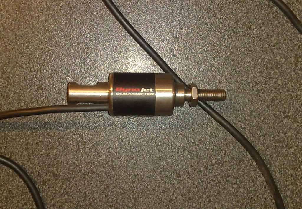
Having laid out the loom and also adding to the mix the logging dash and quick shifter there is a huge
Amount of wiring and hacking into to a loom to shorten it is one thing but it can get really confusing when adding more things and it had to be routed tidy and be accessible too.
I wanted to get on it but I only wanted to do it once!! I printed off the wiring diagram and took the wiring diagram for the quick shifter and logger too and sat on the living room floor for an entire evening just working out what was to be lost and where to splice in the new stuff and the relevant colours......... This was a real nightmare!!! AGGHHHHHHHHHHH The worst bit is that it seems that for all the hard work nothing has actually been done!
Back at the workshop �.. I Connected all the original loom together to be sure it worked so that I knew I had a reliable base to start from.
The bike started OK so everything was taken off so the butchery could begin.
Also the clock mount I�d previously made was no good so a new template was made and welded onto the fairing mount for the dash.

I also realised It might be easier to work from the back of the bike forward as there was less at the back.
First off I needed to list all the channels for the logger so everything was included in the loom and I hopefully didn�t need to open it up again later to add something.
Sensors decided on were:
1.Speed sensor
2.TPS
3.Water temp
4.RPM
5.Brake Pressure
6.Gyroscope
It will also have a gear indicator and voltage monitor.
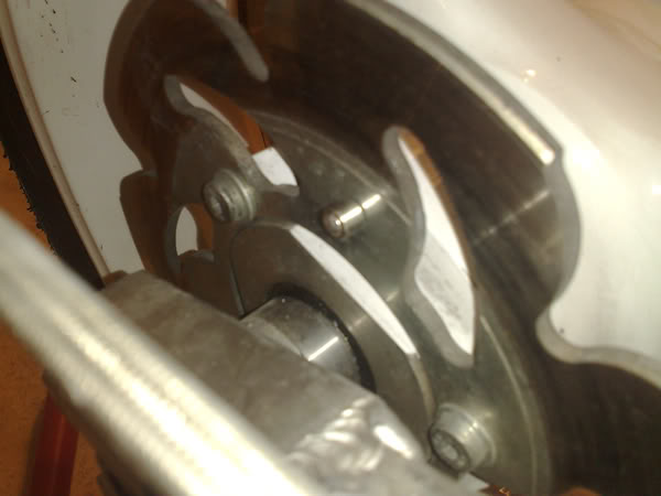
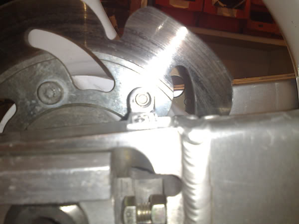
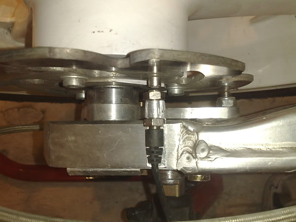
OK the rear most wiring then bearing in mind that there will only be a daytime MOT ( No lights needed at the back ) will be the speed sensor which uses a magnet positioned somewhere on the wheel.
I�ve made up and mounted a very basic bracket on the swing arm and drilled and fixed the magnet to the rear disc. This does not foul the calliper and also when the bike is crashed the sensor and bracket is likely to be fairly well protected.

Well its been a busy week and I�ve got a load done plus some planning and head scratching too.
Having laid out the loom and also adding to the mix the logging dash and quick shifter there is a huge
Amount of wiring and hacking into to a loom to shorten it is one thing but it can get really confusing when adding more things and it had to be routed tidy and be accessible too.
I wanted to get on it but I only wanted to do it once!! I printed off the wiring diagram and took the wiring diagram for the quick shifter and logger too and sat on the living room floor for an entire evening just working out what was to be lost and where to splice in the new stuff and the relevant colours......... This was a real nightmare!!! AGGHHHHHHHHHHH The worst bit is that it seems that for all the hard work nothing has actually been done!
Back at the workshop �.. I Connected all the original loom together to be sure it worked so that I knew I had a reliable base to start from.
The bike started OK so everything was taken off so the butchery could begin.
Also the clock mount I�d previously made was no good so a new template was made and welded onto the fairing mount for the dash.
I also realised It might be easier to work from the back of the bike forward as there was less at the back.
First off I needed to list all the channels for the logger so everything was included in the loom and I hopefully didn�t need to open it up again later to add something.
Sensors decided on were:
1.Speed sensor
2.TPS
3.Water temp
4.RPM
5.Brake Pressure
6.Gyroscope
It will also have a gear indicator and voltage monitor.
OK the rear most wiring then bearing in mind that there will only be a daytime MOT ( No lights needed at the back ) will be the speed sensor which uses a magnet positioned somewhere on the wheel.
I�ve made up and mounted a very basic bracket on the swing arm and drilled and fixed the magnet to the rear disc. This does not foul the calliper and also when the bike is crashed the sensor and bracket is likely to be fairly well protected.
#24
05-03-2010, 03:37 PM
Join Date: Feb 2010
Location: LANCS UK
Posts: 76
Likes: 0
Received 0 Likes
on
0 Posts

#25
05-04-2010, 12:47 AM

Member
Join Date: Aug 2007
Location: San Diego CA
Posts: 2,609
Likes: 0
Received 0 Likes
on
0 Posts
#27
05-04-2010, 03:23 PM
Join Date: Feb 2010
Location: LANCS UK
Posts: 76
Likes: 0
Received 0 Likes
on
0 Posts
#28
05-06-2010, 04:14 AM
Join Date: Feb 2010
Location: LANCS UK
Posts: 76
Likes: 0
Received 0 Likes
on
0 Posts
Hey all thanks for all the encouragement!!!
�.as we had a bank holiday here last weekend I did do a whole lot on Monday whilst keeping an eye on the BSB highlights! It certainly kept me going ..I didn't get chance to post it all up so here is a quick recap ...............
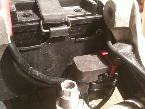
The wiring is getting very confusing as I�ve had to open up the entire loom to remove the road lighting bits. I also have to mount the ignitor and reg/rec and solenoid switch as these are the next lot of parts closest to the rear of the bike and sow in the speed sensor wire into the loom. I�m trying to keep any fragile parts inside the frame as an off might well damage them so they�ll be tucked in close to the battery. The sub frame is a racing alloy one and not much room there. Keeping the solenoid next to the battery was a logical move and was the first simple job just cable tied to the plastic battery case and gives good access to the main fuse. The Main wire leading to the starter motor will be run close to the LHS frame spar so the fuse/solenoid will be to the left of the rear ride height adjuster.
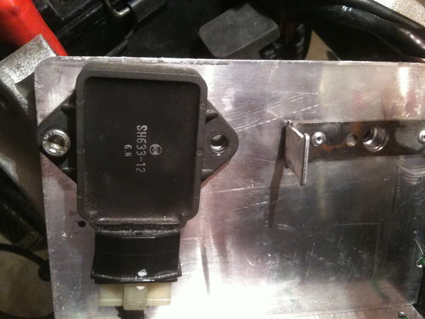
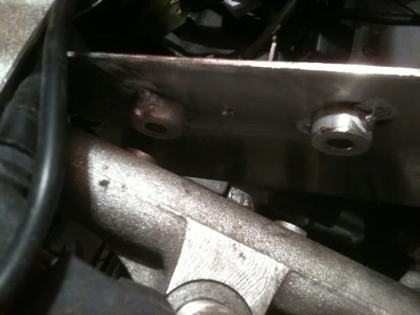
This was a very simple alloy plate folded at the bottom and I�ve riveted the original blade ignitor bracket in position but countersunk the allen head bolt so that when its seated it�ll allow the ignitor to sit back in its proper place. If you�re wondering how you lose the thickness of an allen bolt in a thin alloy plate ? I�ve turned up some alloy spacers so that the plate sits off the frame bar and the back of the fixings for the reg/rec don�t foul.
�.as we had a bank holiday here last weekend I did do a whole lot on Monday whilst keeping an eye on the BSB highlights! It certainly kept me going ..I didn't get chance to post it all up so here is a quick recap ...............
The wiring is getting very confusing as I�ve had to open up the entire loom to remove the road lighting bits. I also have to mount the ignitor and reg/rec and solenoid switch as these are the next lot of parts closest to the rear of the bike and sow in the speed sensor wire into the loom. I�m trying to keep any fragile parts inside the frame as an off might well damage them so they�ll be tucked in close to the battery. The sub frame is a racing alloy one and not much room there. Keeping the solenoid next to the battery was a logical move and was the first simple job just cable tied to the plastic battery case and gives good access to the main fuse. The Main wire leading to the starter motor will be run close to the LHS frame spar so the fuse/solenoid will be to the left of the rear ride height adjuster.
This was a very simple alloy plate folded at the bottom and I�ve riveted the original blade ignitor bracket in position but countersunk the allen head bolt so that when its seated it�ll allow the ignitor to sit back in its proper place. If you�re wondering how you lose the thickness of an allen bolt in a thin alloy plate ? I�ve turned up some alloy spacers so that the plate sits off the frame bar and the back of the fixings for the reg/rec don�t foul.
#29
05-06-2010, 06:53 AM

Senior Member
Join Date: Nov 2008
Location: J-ville, FLORIDA
Posts: 739
Likes: 0
Received 0 Likes
on
0 Posts
#30
05-06-2010, 12:14 PM
Join Date: Feb 2010
Location: LANCS UK
Posts: 76
Likes: 0
Received 0 Likes
on
0 Posts