Planning on Adjusting Valve Clearances
#31
 02-17-2008, 09:12 AM


Well, here we go. I started on Sat around 9am or so. I stopped aroud 3 in the afternoon when I found that none of the Honda dealers had the shims I needed.
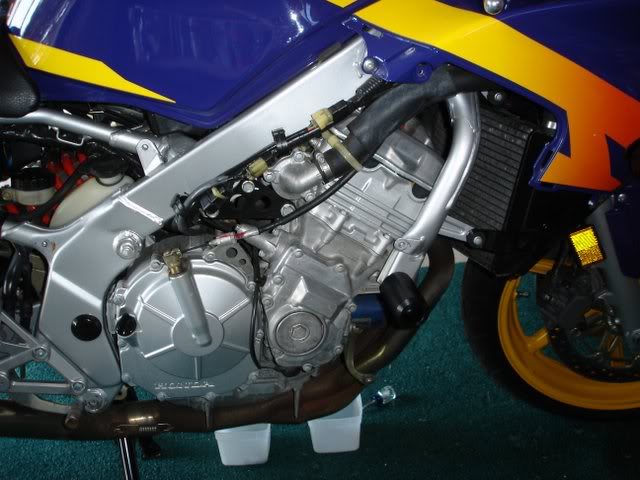
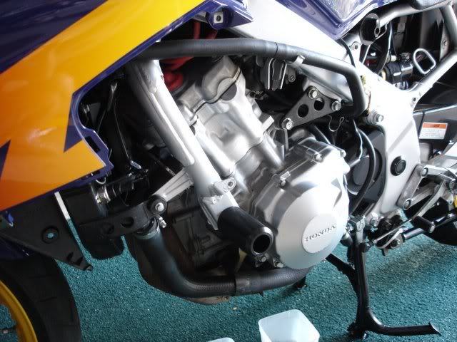
The first thing I needed to do was to get all the skins off. I had originally intended to just take the lowers off, but it's easier to get the radiator down and out of the way.
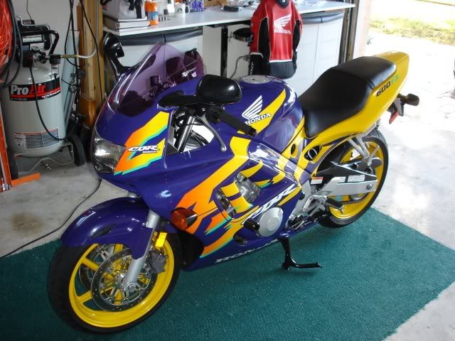
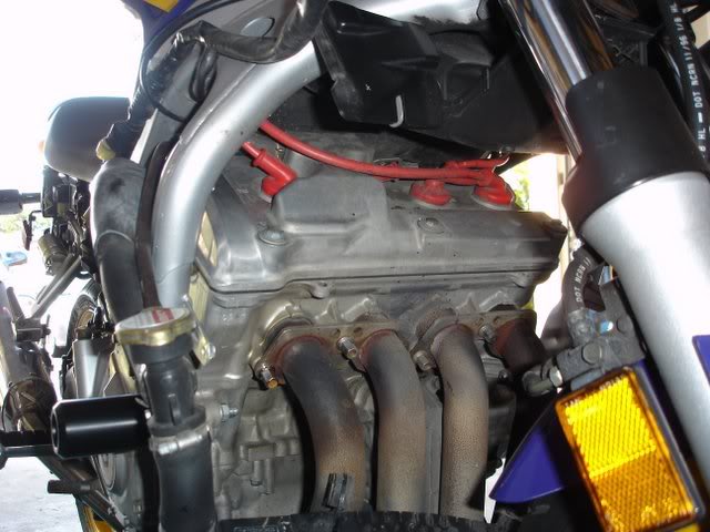
Here she is in all her glory. With views of each side.
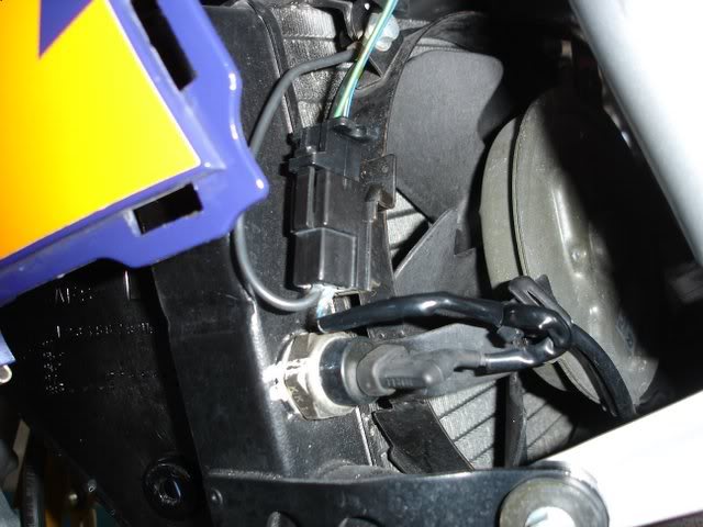
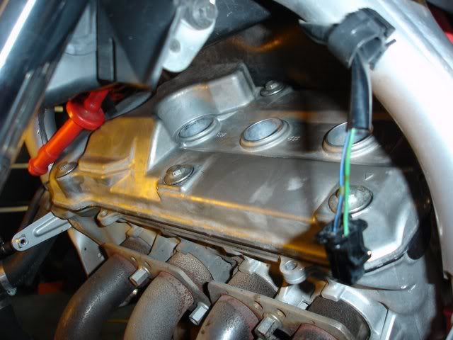
There's an electrical connection to the radiator fan that you need to disconnect to allow radiator to be lowered out of the way. You don't need to disconnect any of the hoses to do this work. Simply removing the bolts that it hangs from and down she'll go.
Here's that connector on the left side. It's the upper one with the green and white striped wire.
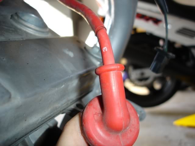
Next would be to unplug the sparkplug wires and move them out of the way.
I'm not sure if they're all like this, but there are numbers on the plug wires to keep you from putting them back in the wrong place. Also from their length, it would be difficult to ge them mixed up and put on the wrong plug.
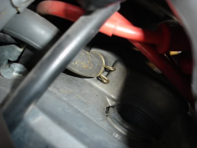
There's a hose that's attached at the rear of the cylinder head cover that's easily removed as well. A pair of plyers, a little squeeze to slide the clamping ring up the hose a little. Then a little encouragement from a flat blade screwdriver and the hose will slide off.
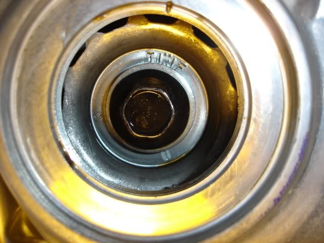
Next, remove the inspection cover from the right side of the engine case where the timing pulse rotor is located. Behind it you see a bolt that you turn "CLOCKWISE" to rotate the crankshaft to align the various index marks as indicated by the shop manual. Make sure you've got a copy of the instructions before attempting to do this. The "T" mark is the mark next to the letter "T" that's stamped into the metal. They're not talking about the actual letter "T" itself. The mark gets lined up with a notch in the engine case to begin with.
Before you begin turning the crankshaft to position it, you need to use the special tool on the cam chain tensioner. This takes the tension off of the cam chain in case you need to remove the camshafts if you find any of the shims need to be replaced. I didn't have their special tool, but the shop manual gives you instructions on how to make one. If you've ever worked on a PC, then your familiar with the little slot covers at the rear of the case that plug the slots when you dont' have a card in a particular slot. That's what I used to construct the tool.
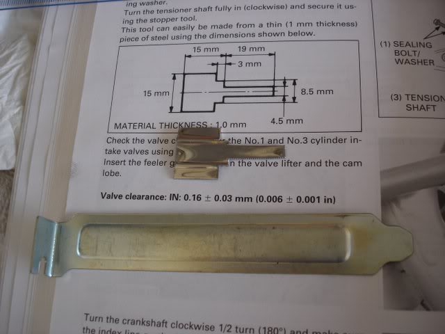
Some tin snips and a little measuring and it was pretty easy.
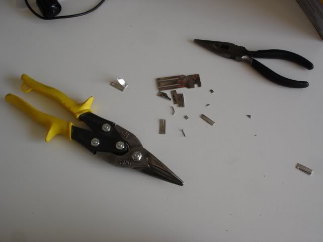
Until I made the tool and followed the instructions on how to use it, I really didn't understand what it was actually doing. You know how when you turn the handle on a door ****, if you let go of the ****, it springs back. Well this is similar to what you're doing with this tool. You insert it into the end of the cam chain tensioner and it engages with a slotted screw down inside it. You turn
The first thing I needed to do was to get all the skins off. I had originally intended to just take the lowers off, but it's easier to get the radiator down and out of the way.
Here she is in all her glory. With views of each side.
There's an electrical connection to the radiator fan that you need to disconnect to allow radiator to be lowered out of the way. You don't need to disconnect any of the hoses to do this work. Simply removing the bolts that it hangs from and down she'll go.
Here's that connector on the left side. It's the upper one with the green and white striped wire.
Next would be to unplug the sparkplug wires and move them out of the way.
I'm not sure if they're all like this, but there are numbers on the plug wires to keep you from putting them back in the wrong place. Also from their length, it would be difficult to ge them mixed up and put on the wrong plug.
There's a hose that's attached at the rear of the cylinder head cover that's easily removed as well. A pair of plyers, a little squeeze to slide the clamping ring up the hose a little. Then a little encouragement from a flat blade screwdriver and the hose will slide off.
Next, remove the inspection cover from the right side of the engine case where the timing pulse rotor is located. Behind it you see a bolt that you turn "CLOCKWISE" to rotate the crankshaft to align the various index marks as indicated by the shop manual. Make sure you've got a copy of the instructions before attempting to do this. The "T" mark is the mark next to the letter "T" that's stamped into the metal. They're not talking about the actual letter "T" itself. The mark gets lined up with a notch in the engine case to begin with.
Before you begin turning the crankshaft to position it, you need to use the special tool on the cam chain tensioner. This takes the tension off of the cam chain in case you need to remove the camshafts if you find any of the shims need to be replaced. I didn't have their special tool, but the shop manual gives you instructions on how to make one. If you've ever worked on a PC, then your familiar with the little slot covers at the rear of the case that plug the slots when you dont' have a card in a particular slot. That's what I used to construct the tool.
Some tin snips and a little measuring and it was pretty easy.
Until I made the tool and followed the instructions on how to use it, I really didn't understand what it was actually doing. You know how when you turn the handle on a door ****, if you let go of the ****, it springs back. Well this is similar to what you're doing with this tool. You insert it into the end of the cam chain tensioner and it engages with a slotted screw down inside it. You turn
#32
02-17-2008, 10:48 PM

Registered Users
Join Date: Jan 2007
Location: Marietta, Ga
Posts: 466
Likes: 0
Received 0 Likes
on
0 Posts
 How many miles on the bike? lol how do you feel about a carb sync tutorial
#33
02-17-2008, 11:08 PM
I'll try to finish what I can tomorrow night. I won't be able to complete all until I get the shims I need. They're supposed to be here by this Friday. I will probably be doing a carb sync afterword. I've read here that it's a good idea after adjusting the valve clearances. As for mileage, she has 33,000 miles on her. We've had it for about 1.5 years and she had 14K miles on her. My wife really likes to ride. They're all her miles.
#34
02-18-2008, 08:16 PM
Ok, where was I..., Oh yea, I checked the clearances and determined that 4 of them were out of spec and would need to be replaced.
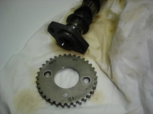
Once you've checked all your clearances, you need to remove the cam shaft covers and the camshafts. Before doing so, you need to remove the sprockets on the ends of the shafts. There are 2 bolts holding the sprockets to the ends of the shafts. Just rotate the crankshaft clockwise so you can get at the bolts. Be carefull not to allow the bolts or sprocketsto fall into the engine. Also tie a string or cable around the timing chain so it doesn't fall into the engine either. Although the sprockets are the same part number,it's probably best to put the sprockets back in their original place. They probably pick up a wear pattern from the chain over time and they might be subject to additional wear if you were to swich them around. Here is the camshafts with the sprockets off of them.
If you look closely at the top of the cam shaft covers, there are numbers right next to the bolts. Well, these are for the removal and tightening sequence. It's a criss cross pattern.These covers are precision manufactured to hold the cam shafts in place while allowing oil to circulate around them. Keep in mind that this cover is holding the cam shaft in place against the force of some, but not all of the valve springs. That's because only some of the valves are open at one time. As you loosen the bolts the valve springs are pushing the camshaft up which will put uneven tension on the cover. It's important to loosen the bolts gradually and evenly so the cover comes straight up. At some point it may be necessary to give the cover some encouragement. Be carefull how you do this. You don't want to damage any of the gasket surfaces or machined surfaces.
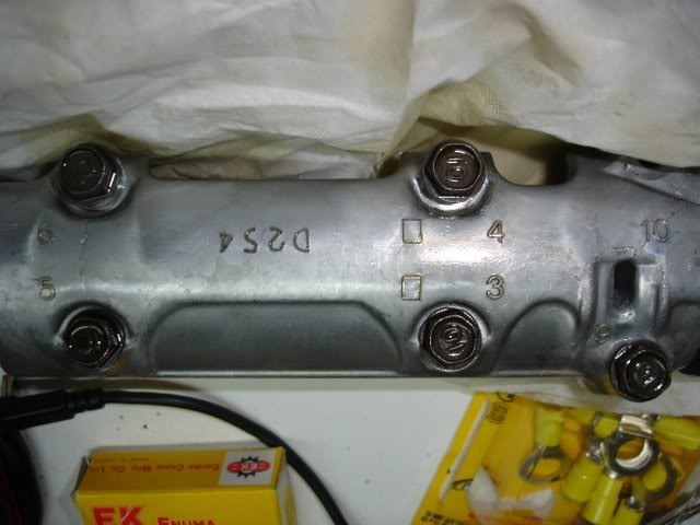
Here are the numbers next to the bolts indicating the sequence for loosening.
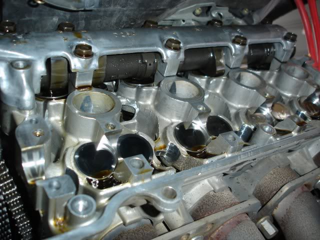
In this image one of the camshafts has been removed and I've begun loosening the intakes cover.
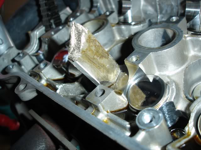
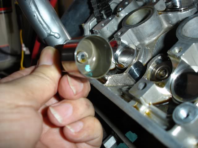
I'm only removing 4 of the lifters, which resemble polished bottle caps. With a magnet, they lift right out very easily.
You can see here as they slide up
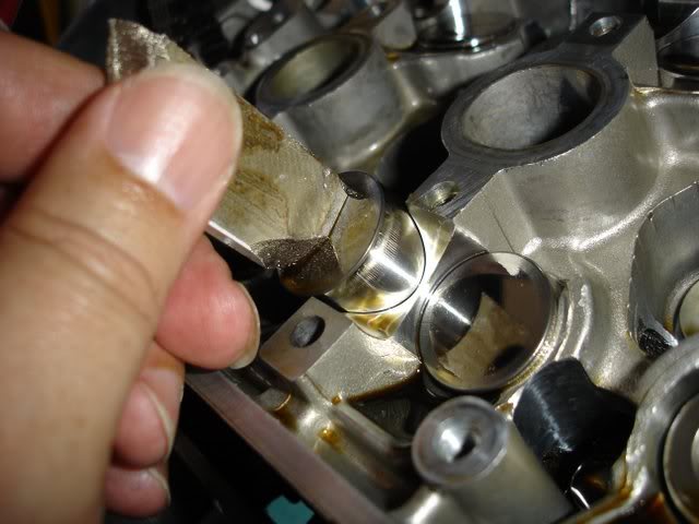
When I turn it over you can see the shim stuck to the inside of the lifter. If you look at where it just came from, you can see in the center of the opening the small round end of the valve stem itself.
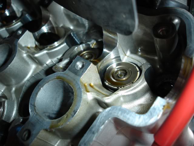
This is the #1 intake valves with the lifters removed.
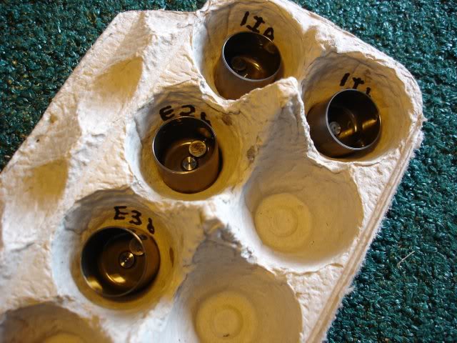
I used an egg carton lid to put the lifters in along with the existing shims. The shims have numbers on them indicating their thickness.
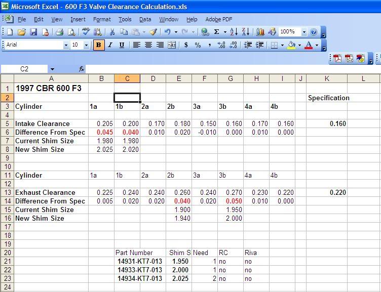
I used this excel file to help with the calculations. It's actually pretty easy. I recorded the measured clearance for each of the intake and exhaust valves. At the far rightI recorded what the spec was supposed to be for intake and exhaust. For intake, it was .16mm +- .03mm and for exhaust it was .22mm +- .03mm. For those that were out I removed the lifter and measured and recorded the current shim thickness. You should m
Once you've checked all your clearances, you need to remove the cam shaft covers and the camshafts. Before doing so, you need to remove the sprockets on the ends of the shafts. There are 2 bolts holding the sprockets to the ends of the shafts. Just rotate the crankshaft clockwise so you can get at the bolts. Be carefull not to allow the bolts or sprocketsto fall into the engine. Also tie a string or cable around the timing chain so it doesn't fall into the engine either. Although the sprockets are the same part number,it's probably best to put the sprockets back in their original place. They probably pick up a wear pattern from the chain over time and they might be subject to additional wear if you were to swich them around. Here is the camshafts with the sprockets off of them.
If you look closely at the top of the cam shaft covers, there are numbers right next to the bolts. Well, these are for the removal and tightening sequence. It's a criss cross pattern.These covers are precision manufactured to hold the cam shafts in place while allowing oil to circulate around them. Keep in mind that this cover is holding the cam shaft in place against the force of some, but not all of the valve springs. That's because only some of the valves are open at one time. As you loosen the bolts the valve springs are pushing the camshaft up which will put uneven tension on the cover. It's important to loosen the bolts gradually and evenly so the cover comes straight up. At some point it may be necessary to give the cover some encouragement. Be carefull how you do this. You don't want to damage any of the gasket surfaces or machined surfaces.
Here are the numbers next to the bolts indicating the sequence for loosening.
In this image one of the camshafts has been removed and I've begun loosening the intakes cover.
I'm only removing 4 of the lifters, which resemble polished bottle caps. With a magnet, they lift right out very easily.
You can see here as they slide up
When I turn it over you can see the shim stuck to the inside of the lifter. If you look at where it just came from, you can see in the center of the opening the small round end of the valve stem itself.
This is the #1 intake valves with the lifters removed.
I used an egg carton lid to put the lifters in along with the existing shims. The shims have numbers on them indicating their thickness.
I used this excel file to help with the calculations. It's actually pretty easy. I recorded the measured clearance for each of the intake and exhaust valves. At the far rightI recorded what the spec was supposed to be for intake and exhaust. For intake, it was .16mm +- .03mm and for exhaust it was .22mm +- .03mm. For those that were out I removed the lifter and measured and recorded the current shim thickness. You should m

#36
02-19-2008, 09:28 PM
Thanks for the positive feedback and support. Your input and photo's made it much easier as I knew what to expect. It's taken longer than I expected, but stopping to take photos and thinking about what someone might want to see takes extra time. But I think it's worth it. I figure it's my little part in giving back to the forum because clearly I've taken a lot from it.
#37
03-07-2008, 09:34 PM
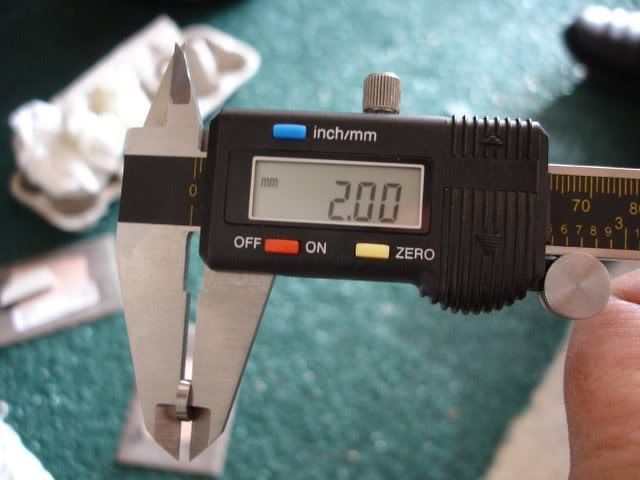
Well, I've finished it. The last shim, a 2.000 mm shim finally came in last Friday. I installed them on Saturday and put the top end back together. Since I had also decided to do the carbs as well, I had to waituntil Monday for the gaskets to come in before testing it. I didn't take as many photo's putting it back together. I figure you can just reverse everything here. I did take a few and I'll post here. Getting the cams in the right position and the cam chain and sprockets back in the exact location was a challenge I will say. I forgot that I had rotated the crankshaft a few times during the clearance checking stage. I had to take the sprockets off the cams, rotate the crankshaft and cam chain (without letting it fall into the engine) and put things back together again.
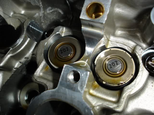
Here I've put the shims in the locations that needed them. The closest size for the intake valves was a 2.025 mm shim for each one. On 2 other cylinders I needed 2 different sizes.
Here I'm preparing the cams and camshaft covers. I didn't have any Molybdenum Disulfide Oil ( a 50/50 mix of engine oil and Molybdenum Disulfide Grease) so I mixed Mobile 1 Synthetic Grease and Synthetic oil in the same ratio. I coated the cam lobes, journals, and bearing surfaces on the cover and cylinder head with this mixture.
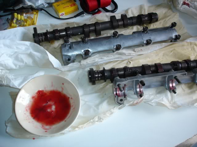
I did verify that if the shim said 2.000 mm that it was actually that.
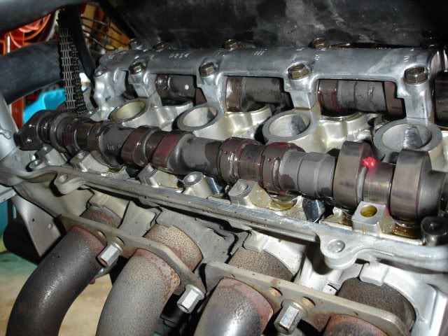
Here i've installed the intake cam and placed the exhaust cam in place before putting the camshaft cover on it. I cleaned the camshafts thoroughly with carb cleaner. They were spotless before putting in. The moving parts were coated with my mixture (although in the photo it looks like the first 2 lobes are dry, trust me, they're not) before putting it in.
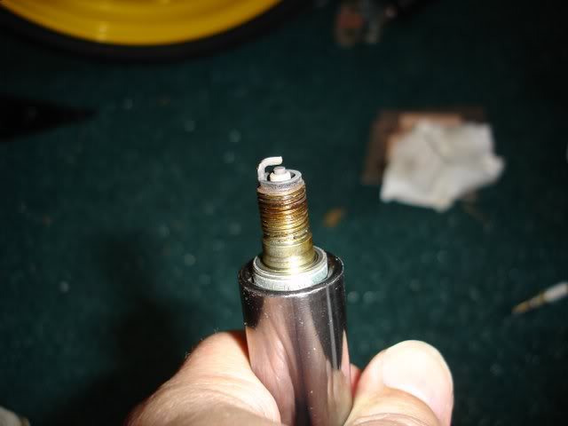
The plugs looked good, but since I was there, what the heck.
All nice and cleaned up. I really cleaned the head cover well. I put in a new gasket as well as bolt gaskets. I used a very small amount of silicone sealant in the cover to hold the gasket in place while I positioned it, as well as in the curved parts as indicated by the manual.
Well on Monday I put the new gaskets in the carburetors and put it all back on the bike. Maybe I'll do something on carb cleaning in the future. When I got it started (it helps to use the choke) It sounded real good, no unusual noises (Thank you god) and no leaks. Weather has been poor all week, so we rode them to dinner tonight. My wife thinks that it seems smoother, a little more responsive, and she's happy to have it back. Tomorrow we'll take them on a 250 mile ride to Clearwater, FL (central West coast of Florida) for a good shake down ride. I'm not anticipating any problems at all.
Thanks everyone for taking the time to read this long post.
Here I've put the shims in the locations that needed them. The closest size for the intake valves was a 2.025 mm shim for each one. On 2 other cylinders I needed 2 different sizes.
Here I'm preparing the cams and camshaft covers. I didn't have any Molybdenum Disulfide Oil ( a 50/50 mix of engine oil and Molybdenum Disulfide Grease) so I mixed Mobile 1 Synthetic Grease and Synthetic oil in the same ratio. I coated the cam lobes, journals, and bearing surfaces on the cover and cylinder head with this mixture.
I did verify that if the shim said 2.000 mm that it was actually that.
Here i've installed the intake cam and placed the exhaust cam in place before putting the camshaft cover on it. I cleaned the camshafts thoroughly with carb cleaner. They were spotless before putting in. The moving parts were coated with my mixture (although in the photo it looks like the first 2 lobes are dry, trust me, they're not) before putting it in.
The plugs looked good, but since I was there, what the heck.
All nice and cleaned up. I really cleaned the head cover well. I put in a new gasket as well as bolt gaskets. I used a very small amount of silicone sealant in the cover to hold the gasket in place while I positioned it, as well as in the curved parts as indicated by the manual.
Well on Monday I put the new gaskets in the carburetors and put it all back on the bike. Maybe I'll do something on carb cleaning in the future. When I got it started (it helps to use the choke) It sounded real good, no unusual noises (Thank you god) and no leaks. Weather has been poor all week, so we rode them to dinner tonight. My wife thinks that it seems smoother, a little more responsive, and she's happy to have it back. Tomorrow we'll take them on a 250 mile ride to Clearwater, FL (central West coast of Florida) for a good shake down ride. I'm not anticipating any problems at all.
Thanks everyone for taking the time to read this long post.

Thread
Thread Starter
Forum
Replies
Last Post