
Chinese SS182 digital speedo installation tips


Thread Starter
|
Senior Member
Joined: Apr 2014
Posts: 257
Likes: 1
From: Bainbridge Is., WA
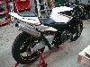
Honda offered a lot of cool optional race parts for the CB77 and there are some pretty decent reproductions around. What I am shooting for is sort of a period correct looking club racer. I would use aftermarket mufflers, seat, shocks and a few other things that emulate the original optional parts. Kinda like this image from somewhere on the interweb:

Attached a pic of what I originally brought home in a basket.
Attached a pic of what I originally brought home in a basket.
Last edited by Doc B.; Oct 20, 2016 at 07:00 PM.
Thread Starter
|
Senior Member
Joined: Apr 2014
Posts: 257
Likes: 1
From: Bainbridge Is., WA
Shoot, looks like whatever free image hosting site I used back when I was posting here got rid of images I linked in this thread and Denny's RR thread. I'll see if I can resurrect any of them and link them from my server. edit - Replaced two of the missing images from this thread. The third one I'm afraid is lost, but there is a written description that should explain what it was.
Last edited by Doc B.; Oct 20, 2016 at 06:55 PM.

Junior Member
Joined: Oct 2016
Posts: 3
Likes: 0
Hey Doc B. wonderful thread. May I ask and if it has already been answered please forgive me but, are you willing to help those in need. I do not have a Honda but I do have a kawasaki with all the schematics and info needed. I seem to have a copy of the copy and there instructions were sad to say the least. I had previously grafted a different model speedo on to my bike with out issue and posted it to my forums for others but I am having a tough go at this one. When I hooked it up everything just flickers and does not light up at all. I am wondering if we pm'ed or emailed each other whether you would mind helping out? Let me know either way and thank you for your time!
Thread Starter
|
Senior Member
Joined: Apr 2014
Posts: 257
Likes: 1
From: Bainbridge Is., WA
As I mentioned before my memory of the details of the install is kind of foggy after two or three years. I'm happy to try to help, but not sure how much help I can be with the fake fake as I have not had hands on with one.
I'd guess that if everything is flickering it may be a bad connection in the 12V supply wiring somewhere, or a bad ground connection. Check those connections and also check to see if there is a miswire of any of the other connections. It would be worth checking the integrity of the plug connection on the back of the unit too. Basically, wiggle it and see if it changes anything.
I'd guess that if everything is flickering it may be a bad connection in the 12V supply wiring somewhere, or a bad ground connection. Check those connections and also check to see if there is a miswire of any of the other connections. It would be worth checking the integrity of the plug connection on the back of the unit too. Basically, wiggle it and see if it changes anything.
Junior Member
Joined: Oct 2016
Posts: 3
Likes: 0
Doc b,
I stepped away and cleared my head and everything is fine except for the Tach. I suspect it is the same issue you originally had with the signal as I recall the ZRX set up is very similar to yours. I fished out my soldering station and will re read this thread and begin the process of hunting for a useable signal. I do not have a scope but could get ahlod of one. The fake-fake seems to be a good one as it mirrors the fake lol. Cheers for now and thank you for the reply!
I stepped away and cleared my head and everything is fine except for the Tach. I suspect it is the same issue you originally had with the signal as I recall the ZRX set up is very similar to yours. I fished out my soldering station and will re read this thread and begin the process of hunting for a useable signal. I do not have a scope but could get ahlod of one. The fake-fake seems to be a good one as it mirrors the fake lol. Cheers for now and thank you for the reply!
Junior Member
Joined: Oct 2016
Posts: 3
Likes: 0
Oh actually I have one question seems the petrol level is full (as it should be ) when the key is on but engine off. When engine is running fuel reads zero, it is working backwards. It is a resistor-float type so I am not sure how to reverse that.

Senior Member
Joined: May 2010
Posts: 417
Likes: 1
From: Saratoga, California
This is still the best thread on the net for clones of clones of Koso dashes. Sorry to flog this horse again, but.... I got one 2 years ago, installed it recently, put the capacitor and resistor in, no dice. I did get the unit to beep at me. Anyone ever get a beep? Plus, every so often when changing between different cap/resist setups, the needle will twitch. Oh, and one last thing, flashing temp and gas gauge leds. My bike is a 91 600 f2. No gas gauge. Tnx.
Thread Starter
|
Senior Member
Joined: Apr 2014
Posts: 257
Likes: 1
From: Bainbridge Is., WA
To clarify, I have never even seen the fake fake, aside from a pic of the insides in this thread. So I don't really have any concrete advice to offer. Without a scope to see what is happening at the connection of the ECU to the tach it's pretty much guesswork as to what is going on. The issue seems to be that either the signal has a DC voltage riding on it that needs to be blocked or given a solid ground reference, the signal is simply too big for the tach input, or there is some kind of polarity issue. I would suggest the following sequence of things to try between the tach signal wire from the ECU and the tach input on the fake fake -
first just a cap, between those two wires. Probably around .1 uF, maybe .01 uF instead if .1 doesn't work. That would block any DC component that might confuse the tach
if that does not work, try adding a 100K ohm resistor from the connecting point of the cap and the tach input to ground. That should create a stable ground reference for the signal and may clean up the signal.
if that does not work try moving the resistor so it is connected from the ECU output and cap connection at one end and ground at the other end.
if that does not work try taking out the cap and connecting the ECU output and tach input together, with the resistor to ground connected at that junction. That may pull the tach signal ground reference point to something the tach is happy with.
If that doesn't work try lifting the grounded end of the resistor and reconnecting the resistor between the between the ECU output and tach input. That might reduce the ECU signal.
When you say the needle will twitch - is that at random, or does it happen right when you connect or disconnect something? If it's random, make sure you have really good ground connections.
I am waiting for someone to buy one of these that turns out to be completely empty inside. The fake/fake/fake.

