When you click on links to various merchants on this site and make a purchase, this can result in this site earning a commission. Affiliate programs and affiliations include, but are not limited to, the eBay Partner Network.
This is great! That's not original fuel-pump relay, which is rectangular with 2-wire connector. Remove that relay and all attached wires. Note which harness wires they were attached to, then disconnect and cover up wound in original wiring.
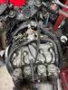
In last photo, is that wire with ring-terminal showing some bubbling and melted insulation?
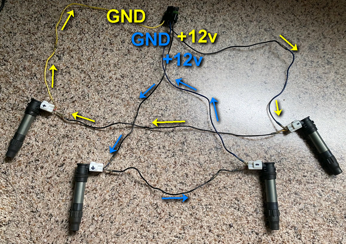
Not able to figure how those coils are connected. Can you untape and spread out wires? I'm working up diagram of how those stick coils should be wired. Then you can compare with what you have.
order left to right is 1234.
Y/Bu & Bl = Y & Bl on plug
Bu/Y & Bl =Bu & Bl on plug
I am not 100% sure if the PO has the + & - marked on the coils correctly...I am assuming so.
Also note he has a spot on the wires where the wire changes from Bl to Bu
Are you taking about blu/yel and yel/blu wires in back not connected to anything? Those are ground wires for coil circuit. Remember how you had already measured 11.65v at coils themselves? The other side of that circuit has to be ground for current to flow. So ignitor grounds those blu/yel and yel/blu wires to flow current through coil from blk/white wires.
Can't measure ground pulses with voltmeter. You can connect 'noid light which will blink when there's grounding pulses. Or use oscilloscope:
Coils have power full-time by default. Then for short time segment, ignitor grounds other side of primary to dump magnetic-field and fire plugs.
Are you saying I should ground those two unconnected blu/Yel and Yel/Blu wires to the bike?
I highlighted in yellow, a black wire that goes from the rectifier to where it was taped with blue electrical tape, went into the same wiring harness as the coil wires and also branched off and changed to red wire that goes into that relay. When I put the volt meter on that black wire and grounded the other mm probe, (with the key on) it indicated 12 volts.
I highlighted in yellow, a black wire that goes from the rectifier to where it was taped with blue electrical tape, went into the same wiring harness as the coil wires and also branched off and changed to red wire that goes into that relay. When I put the volt meter on that black wire and grounded the other mm probe, (with the key on) it indicated 12 volts.
Can you show where black wire connects to red? Red is just branch off black right? And black continues on to fuse-G in fuse-box as well as start/stop switch? If so, you can remove relay and all its wires since fuel-pump is no longer used.
See if you can trace where these original blk/wht, yel/blu, blu/yel wires go. Would like to know where they connect on other end through harness:
This is how power-path should flow from front-end:
start/stop switch RUN +12v blk/wht --> Y-split
Y-split 1 --> Spark Unit
Y-split 2 --> ignition coils
I think you've already traced this in your original power testing and found identical power at both ignition-unit and coils.
Now we just need to figure out where ground-trigger wires blu/yel and yel/blu goes.
Last edited by dannoxyz; Aug 25, 2022 at 12:30 PM.
Can you show where black wire connects to red? Red is just branch off black right? And black continues on to fuse-G in fuse-box as well as start/stop switch? If so, you can remove relay and all its wires since fuel-pump is no longer used.
See if you can trace where these original blk/wht, yel/blu, blu/yel wires go. Would like to know where they connect on other end through harness:
This is how power-path should flow from front-end:
start/stop switch RUN +12v blk/wht --> Y-split
Y-split 1 --> Spark Unit
Y-split 2 --> ignition coils
I think you've already traced this in your original power testing and found identical power at both ignition-unit and coils.
Now we just need to figure out where ground-trigger wires blu/yel and yel/blu goes.
I can see where this forum will see so many new owners of these older bikes for generations! Maybe if it is safe, we could throw our VINs on here and when a google (or whatever) search is done on a vin, then we could see its history.
I am not sure if this will help, but I found the previous owners post that talks about his mods on this bike back in 2012!
https://cbrforum.com/forum/cbr-1000f...1000-a-147631/ Stainless braided steel brake lines front and rear Race craft springs and gold valves K and N air filter Vance and Hines 4-1 with center stand still remaining on Ignition advance and shifter roller bearing and spring upgrade
Ignition coil mod Carbs re-jetted DDM 55w High low Headlight Removed fuel pump and went to gravity feed 3-8 line Maint free AGM battery Corbin Seat Added an accessory30 amp relay and 5 place fuse box, I also fabricated a pair of power outlets. as we are planning a couple of road trips and will need to charge phones, tablets or the occasional electric garment as well as having a battery feed that will take a smart charger, Did many hours of panel repair, bodywork and painting motor,mods carb work and I am pretty proud of it.
Last edited by MN Hurricane; Aug 25, 2022 at 02:12 PM.
Thing is... I don't see any posts where he actually got bike out and running on road... Part he missed is that fuel-pump relay only sends power to pump when engine is spinning!!! It uses ignition-pulses from Spark Unit to pulse relay & pump with each engine-revolution. Higher the RPMs, more pulses per second and more fuel is pumped to match demand. Extremely clever solution. However, people try to test pump with bike not running and it WILL NOT pump! That's intentional design to conform to FMVSS.108 standards. You must crank engine in order to start pump pumping.
Everything's got power, just nothing's triggering coils. Oh, you should pick up
to confirm Spark Unit's triggering sparks. Connect with test-leads one terminal to power, and other to one trigger-wire at a time.
Only thing we need is connect blu/yel and yel/blu wires from stick-coil harness in front to those blu/yel and yel/blu stubs coming from Spark Unit at back of bike.
Just connect these:
to these:
And remove that relay and all non-stock wires connected to it.
Last edited by dannoxyz; Aug 25, 2022 at 05:12 PM.
1351406[/url]]Thing is... I don't see any posts where he actually got bike out and running on road... Part he missed is that fuel-pump relay only sends power to pump when engine is spinning!!! It uses ignition-pulses from Spark Unit to pulse relay & pump with each engine-revolution. Higher the RPMs, more pulses per second and more fuel is pumped to match demand. Extremely clever solution. However, people try to test pump with bike not running and it WILL NOT pump! That's intentional design to conform to FMVSS.108 standards. You must crank engine in order to start pump pumping.
Everything's got power, just nothing's triggering coils. Oh, you should pick up 'noid light to confirm Spark Unit's triggering sparks. Connect with test-leads one terminal to power, and other to one trigger-wire at a time.
Only thing we need is connect blu/yel and yel/blu wires from stick-coil harness in front to those blu/yel and yel/blu stubs coming from Spark Unit at back of bike.
to confirm Spark Unit's triggering sparks. Connect with test-leads one terminal to power, and other to one trigger-wire at a time.
I will need to find a �noid light.
Only thing we need is connect blu/yel and yel/blu wires from stick-coil harness in front to those blu/yel and yel/blu stubs coming from Spark Unit at back of bike.
The fuel pump information is pretty cool to know, do you think those stubby wires somehow connected to the fuel pump so it would pump the same time it would spark?
i checked continuity from the stubs to the corresponding color wires at the black box /6 pin wires and between the stubs and the wires for the coils and it�s all connected. I assume I can cap the stubbies off?


 - of course she does... I know enough about women to be married almost 28 years and some advice from my father in-law "it's cheaper to keep her".