When you click on links to various merchants on this site and make a purchase, this can result in this site earning a commission. Affiliate programs and affiliations include, but are not limited to, the eBay Partner Network.
No volts to the stick coil leads that would have connected to the OEM coils
Hi All,
Please skip to the bold words further down if you are in a hurry.
I am the lucky guy that purchased one of our (late) members bikes. I know motorcycles to a point, I know how to research on the www, hell, I am even old enough to use the dewy decimal system, know the differences between UHF/VHF and can dial a rotary phone with out using a dial, but I cannot figure out why I am not getting 12 volts to the coil wires.
Randy aka rlnelson5 was the previous owner of my 1988 CBR1000f Honda Hurricane before he passed away September 3, 2020, and I had just purchased this bike from is widow. I don't doubt Randy's abilities for working on motorcycles, I have been reading his posts here, but the pictures he shared of it being all done is not what I bought for $500. Basically I am going through everything on this low mileage (6000ish) bike and would like to bring it back to how Randy had it, but it was last on the road in 2015 and then put away wet and naked for 7 years. I am at the point of trying to start the bike, but I get nothing from the coil leads (Randy did upgrade to the stick coil mods) AND every other piece of electrical equipment works perfectly on the bike. I have checked continuity on just about every wire I could access (see manual 17-1-everything) and I am working my way through the maze of wires, connectors and electrical tape.
and now to my question - HOW DO I BYPASS THE ENGINE STOP SWITCH?!!!
I even checked the continuity from the switch to the connector, and it has it. From what I have read on the forum, this bike will still turnover with the stop switch in the off position, but won't allow spark which it does in both the on or off position, but when I held the multimeter on the connecter plugs that the switch is on continuity matches the position of the switch. RUN=continuity Stop = no continuity.
I have checked the ohms of everything related to the coil sticks and everything is within specs. Randy did remove the fuel pump (just left the plug in the bracket), he has what appears to be a homemade relay (probably not homemade)and he ran a red wire from the relay to a fuse holder (minus the fuse, the other half of the holder and the rest of the wire). He had indicated in his notes and on the forum that he wanted to add 12V sockets and hand warmers which were not installed yet. He does have a 40A fuse in the fuse connection for the starter solenoid (which should be 30A). AND I checked the neutral cut off thing and was not able to find a side stand switch, but I don't think there is one on this bike.
DO NOT BYPASS ANYTHING! That is just asking for trouble! Complete meltdown and burning up of bike's harness and bike itself!!! Bike ran perfectly fine leaving showroom floor, and will do it again once you've fixed wiring and restore it back to 100% stock condition.
1. First, replace main-fuse with proper 30a unit. Could very well be shorted wiring somewhere blowing 30a fuse. Perhaps rather than track it down and fix it, he just installed larger fuse. So there may be some melted and burnt wiring somewhere, perhaps power wires to coils even.
2. remove accessory relay, fuse, wirings. Is there only ONE red-wire connecting relay to bike's harness? Then remove that red wire, relay and attached fuse.
3. trace flow of electricity from battery to coils. Where power stops shows problem is between that location and previous one that did have power
- battery voltage = ???
- red wire leaving starter solenoid, volts = ??
- red wire entering ignition-switch, volts = ???
- key ON, red/black wire leaving ig-switch, volts = ???
- key ON, red/black wire entering fusebox, volts = ???
- key ON, black wire leaving fusebox, volts = ???
- key ON, black wire entering start/stop switch, volts = ???
- key ON, start/stop switch = RUN, black/white wire leaving switch, volts = ???
- key ON, start/stop switch = RUN, black/white wire entering spark-unit, volts = ???
- key ON, start/stop switch = RUN, black/white wire entering each coil, volts = ???
4. post circuit-diagram/photos of how stick-coils are attached to factory harness. Originally had twin dual-output coils in wasted-spark configuration. To fit stick-coils, he'd have to split/parallel blue/yellow & yellow/blue trigger wires. But have to run 2 coils' power-wires in series to original black/white power wires to account for lower-impedance of stick-coils.
So having wiring-diagram of how he wired in 4 stick-coils in place of 2 factory inductive coils would really help fix this.
Last edited by dannoxyz; Aug 22, 2022 at 10:21 PM.
DO NOT BYPASS ANYTHING! That is just asking for trouble! Complete meltdown and burning up of bike's harness and bike itself!!! Bike ran perfectly fine leaving showroom floor, and will do it again once you've fixed wiring and restore it back to 100% stock condition.
1. First, replace main-fuse with proper 30a unit. Could very well be shorted wiring somewhere blowing 30a fuse. Perhaps rather than track it down and fix it, he just installed larger fuse. So there may be some melted and burnt wiring somewhere, perhaps power wires to coils even.
2. remove accessory relay, fuse, wirings. Is there only ONE red-wire connecting relay to bike's harness? Then remove that red wire, relay and attached fuse.
3. trace flow of electricity from battery to coils. Where power stops shows problem is between that location and previous one that did have power
- battery voltage = ???
- red wire leaving starter solenoid, volts = ??
- red wire entering ignition-switch, volts = ???
- key ON, red/black wire leaving ig-switch, volts = ???
- key ON, red/black wire entering fusebox, volts = ???
- key ON, black wire leaving fusebox, volts = ???
- key ON, black wire entering start/stop switch, volts = ???
- key ON, start/stop switch = RUN, black/white wire leaving switch, volts = ???
- key ON, start/stop switch = RUN, black/white wire entering spark-unit, volts = ???
- key ON, start/stop switch = RUN, black/white wire entering each coil, volts = ???
4. post circuit-diagram/photos of how stick-coils are attached to factory harness. Originally had twin dual-output coils in wasted-spark configuration. To fit stick-coils, he'd have to split/parallel blue/yellow & yellow/blue trigger wires. But have to run 2 coils' power-wires in series to original black/white power wires to account for lower-impedance of stick-coils.
So having wiring-diagram of how he wired in 4 stick-coils in place of 2 factory inductive coils would really help fix this.
Thank you for the reply Dannoxyz! I have made note of your directions and will get to testing and coming up with a clearer picture of what I am working with/looking at so I can share it with you all. But first I must work...wife says all play an no work makes Rick sleep in the shed.
1. First, replace main-fuse with proper 30a unit. Could very well be shorted wiring somewhere blowing 30a fuse. Perhaps rather than track it down and fix it, he just installed larger fuse. So there may be some melted and burnt wiring somewhere, perhaps power wires to coils even.
DONE
2. remove accessory relay, fuse, wirings. Is there only ONE red-wire connecting relay to bike's harness? Then remove that red wire, relay and attached fuse.
DONE - there are multiple wires going through the relay, so I don’t want to remove the whole thing…or do I?
3. trace flow of electricity from battery to coils. Where power stops shows problem is between that location and previous one that did have power
- battery voltage = 12.8 - red wire leaving starter solenoid, volts = 12.9 - red wire entering ignition-switch, volts = 13 - key ON, red/black wire leaving ig-switch, volts = 12 - key ON, red/black wire entering fusebox, volts = 11.6 - key ON, black wire leaving fusebox, volts = 11.5 - key ON, black wire entering start/stop switch, volts = 11.8 - key ON, start/stop switch = RUN, black/white wire leaving switch, volts = 11.65 - key ON, start/stop switch = RUN, black/white wire entering spark-unit, volts = 11.65 - key ON, start/stop switch = RUN, black/white wire entering each coil, volts = 11.65
4. post circuit-diagram/photos of how stick-coils are attached to factory harness. Originally had twin dual-output coils in wasted-spark configuration. To fit stick-coils, he'd have to split/parallel blue/yellow & yellow/blue trigger wires. But have to run 2 coils' power-wires in series to original black/white power wires to account for lower-impedance of stick-coils.
So having wiring-diagram of how he wired in 4 stick-coils in place of 2 factory inductive coils would really help fix this. Colors used in pic do not represent the wire colors used in the setup.they are mostly just yellow, blue and black (see below pictures).
After I checked the above information, I am still not getting spark on any of the new plugs or wires. As you can tell by the voltages I was charging the battery during these tests.
do you think it would be a good idea to remove the covers from the suspect wiring harnesses?
again thank you for your time and guidance, it is very much appreciated!
2. remove accessory relay, fuse, wirings. Is there only ONE red-wire connecting relay to bike's harness? Then remove that red wire, relay and attached fuse.
DONE - there are multiple wires going through the relay, so I don�t want to remove the whole thing�or do I?
If you can trace the wires from relay to where they connect to factory harness. Then confirm that they are non-factory wires, then remove those multiple wires along with accessory-relay and extra fuse/fusebox.
again thank you for your time and guidance, it is very much appreciated!
Rick
You're most welcome! This is great work! You've confirmed that coils are getting power, so now it's matter of making sure triggers are connected properly.
I'll come up with schematic from these photos and see how they're connected to factory harness.
Yeah, charge up that battery. And disconnect headlight fuse for now so they don't drain battery.
We'll get this going soon enough!
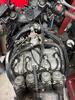
An update to share…I removed the tape on the relay that was in the approximate area where the fuel pump would have been installed. This red wire was grounded to the battery I removed a bunch of electrical tape and found a few things. Purple circle is the wire that was grounded Green circle was just hanging out at the front of the bike, maybe an in-line fuse? Orange circles are two cut off wires (These look important)
I hope this is helpful in figuring out the situation.
Last edited by MN Hurricane; Aug 24, 2022 at 12:09 PM.
remember: There never seems to be enough time to do job right 1st time around. But there's ALWAYS time to do it again!! Often times on side of road in total darkness and rain!!!
and to add to that ... with your wife yelling I told you so!
So sure as $h!t, the cut wires look the same as the coil wires…coincidence? I’m betting not, but I’m not sure why they would have had to go to the fuel pump relay. The PO looks like he capped off the two wires.
Last edited by MN Hurricane; Aug 24, 2022 at 06:23 PM.