When you click on links to various merchants on this site and make a purchase, this can result in this site earning a commission. Affiliate programs and affiliations include, but are not limited to, the eBay Partner Network.
Hi all. I'm replacing some old flush mount led turn signals with same profile flush mount smoke led turn signals. When I connect the new ones wire for wire it doesn't work. The old ones didn't work for a while so I don't know if it's the wiring, the lights or something else.
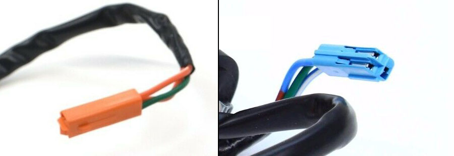
The new signals have a black and a yellow wire. Out of the two harnesses, from one there's an orange with white wire and an orange wire, and from the other there's a green wire. The black was connected to the green, the yellow was connected to the orange. The orange and white wire from the harness was capped off. .When I did the same with the new lights it didn't work. I'm attaching pics.
Does the wiring seem right and I have some other problem?
Your problem doesn’t have anything to do with wiring. You just don’t have any power going out those wires to lights. Learn this, it’s 5-minute fix with multimeter.
You can even install 2x diodes per side and get both marker lights AND blinker functions working just like stock 2-filament bulbs! Better visibility and higher safety!
You’re welcome! To find out where power disappears, do series of measurements to trace electricity flow through circuit:
1. Battery, volts = ???
2. Power into ignition-switch red wire, volts = ???
3. Key On, measure power out of ignition-switch, red/blk, volts = ??
4. measure power out of fusebox wht/grn wire, volts = ??
5. Flip signal switch L or R, measure power into signal switch, gry, volts = ??? (pulsing)
6. measure power at winker bulb wire, O=Left, LiteBlu=right, volts = ??? (pulsing)
You’ll make series of measurements like 13v -> 13v -> 13v -> 0v <— aHAH!!! Problem is between that latest junction measured with zero power and previous measured point that did have power! Most of time it’s corroded signal switch (open up, spray WD40 on contacts, flip switch back & forth). Or broken wire, measure end-to-end to make sure it’s working.




 01 F4i Led Turn signal wiring question