How To: Manual Fan Swith
#1
 10-05-2010, 11:58 PM


I know there are a lot of differences in opinion about a manual fan switch. This post is a How To for anyone who wants information on how to do it.
I forgot to take pictures when I installed the fan switch, if anyone needs pics or more information let me know and I will add them.
What you will need:
1 30A/40A 5 pin SPDT Relay
1 16A Rocker Switch w/LED
18 gauge wire
16 gauge wire
1 16g T-Tap
1 18g male spade connector
3 16g female spade connectors
6 18g female spade connectors
1 18g #4 ring terminal
1/4" Heat shrink tubing
3/8" wire loom
First, you will want to find a location to mount the rocker switch. I mounted mine about the middle of the intake cover just below the bars. This way it was easy to reach when I wanted to turn it on.
Next, remove the intake cover and side fairings on the left side of the bike.
After you have decided on a location for the rocker switch, find a place to attach the relay. I zip tied the relay to the existing harness that runs under the intake tube.
You can now measure the wire needed. (I did not list the wire lengths I used since installations may not be the same)
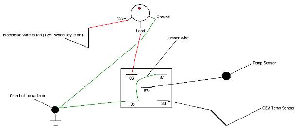
You will need to use the T-Tap to splice into the Black/Blue wire for the fan. This is a 12v+ only when the key is on. Run this wire to the rocker switch and attach to the 12v+ terminal.
Run a new wire from the LOAD on the rocker switch to terminal 86 on the relay.
Remove the OEM connection from the temp sensor, connect the new wire and run to terminal 87a on the relay
Connect a new wire with the male spade connector to the OEM wire you just removed, attach to terminal 30 on the relay.
You will need to run a jumper wire from terminal 87 to terminal 85 on the relay.
From terminal 85 on the relay run a wire with a #4 ring terminal to the 10mm bolt attached to the top of the radiator.
You will also need to run a ground from the rocker switch, I also attached this to the ring terminal. This way I did not have to run 2 seperate grounds.
Below is the diagram of how to wire the relay, etc.
Sorry for any confusion with the write up, I will try and take some pics this weekend to clarify the installation.
I forgot to take pictures when I installed the fan switch, if anyone needs pics or more information let me know and I will add them.
What you will need:
1 30A/40A 5 pin SPDT Relay
1 16A Rocker Switch w/LED
18 gauge wire
16 gauge wire
1 16g T-Tap
1 18g male spade connector
3 16g female spade connectors
6 18g female spade connectors
1 18g #4 ring terminal
1/4" Heat shrink tubing
3/8" wire loom
First, you will want to find a location to mount the rocker switch. I mounted mine about the middle of the intake cover just below the bars. This way it was easy to reach when I wanted to turn it on.
Next, remove the intake cover and side fairings on the left side of the bike.
After you have decided on a location for the rocker switch, find a place to attach the relay. I zip tied the relay to the existing harness that runs under the intake tube.
You can now measure the wire needed. (I did not list the wire lengths I used since installations may not be the same)
You will need to use the T-Tap to splice into the Black/Blue wire for the fan. This is a 12v+ only when the key is on. Run this wire to the rocker switch and attach to the 12v+ terminal.
Run a new wire from the LOAD on the rocker switch to terminal 86 on the relay.
Remove the OEM connection from the temp sensor, connect the new wire and run to terminal 87a on the relay
Connect a new wire with the male spade connector to the OEM wire you just removed, attach to terminal 30 on the relay.
You will need to run a jumper wire from terminal 87 to terminal 85 on the relay.
From terminal 85 on the relay run a wire with a #4 ring terminal to the 10mm bolt attached to the top of the radiator.
You will also need to run a ground from the rocker switch, I also attached this to the ring terminal. This way I did not have to run 2 seperate grounds.
Below is the diagram of how to wire the relay, etc.
Sorry for any confusion with the write up, I will try and take some pics this weekend to clarify the installation.
Last edited by bleheny; 10-06-2010 at 06:25 PM. Reason: Add Picture of diagram
#2
10-13-2010, 12:32 AM

Senior Member
Join Date: Jun 2010
Location: northeast ohio
Posts: 197
Likes: 0
Received 0 Likes
on
0 Posts
#3
10-13-2010, 02:22 AM
#4
10-13-2010, 02:39 AM
Senior Member
Join Date: Jun 2010
Location: northeast ohio
Posts: 197
Likes: 0
Received 0 Likes
on
0 Posts
#5
10-13-2010, 08:08 PM
http://cgi.ebay.com/ebaymotors/HONDA...Q5fAccessories

Thread
Thread Starter
Forum
Replies
Last Post
dracowing14
Other Models (125, 250, 400)
0
12-27-2011 07:24 AM
Trips
CBR 1000F "Hurricane"
20
07-15-2009 10:56 AM
aclarkgto
General Tech
1
02-15-2006 02:41 AM