
electrical components
#41
 06-30-2011, 12:20 PM


Member
Join Date: Apr 2010
Location: Reno, NV
Posts: 65
Likes: 0
Received 0 Likes
on
0 Posts
gave this a little thought, you could take the 555 circuit, and a decade counter(ex 4017), then connect each output of the counter to a D flip flop, if you store the value in the flip flop, you can get your ring to stay turn on. the output of each D flip flop would correspond to an LED.
couple issues i have not given thought to
-how to stop
-how to reset flip flops after/before is it neccesary.
-what if any flip flops can drive enough current/ operate/handle 14 volts.
....tbd
ps you could make a 500ohm resistor from 2 1k in parallell. ie eq. = x *y /(x + y)
to find your resistor value i assume you took (14v -2v(left) -2v(right)) / 20mA = 500ohms, the 560s may be a better value to use so you dont overheat the LEDS- best way to verify this is to take a dmm measure it and verify it works as expected.
I assume you are going to breadboard this out before you solder
pick your resistor values from these tables
http://eet.etec.wwu.edu/etec271/StdRValues.pdf
Id personally use 1% resistors where available.
Tucsondude, did you read any of the posts in this thread before posting this?
Honda125, I didn't know you wanted them to "un-illuminate" in the opposite order that they came on in... That will be MUCH MUCH harder to make happen. However, it's a fairly simple circuit if you just want them to illuminate in a clockwise/counter-clockwise manner and then just shut off all at once when you release the brakes. As for parts, you'll still need to get:
-a 6-bit counter
-555 timer chip (lookup 555 timer and do the calculations to see what value capacitors and resistors you need to make the timer "tick" at the right frequency you want the LEDs to turn on in)
-flip-flops (half the amount of the total LEDs in BOTH taillights, so if you have 22 LEDs in each tailight, you need 22 flip flops)(you should be able to get an IC (chip) that has multiple flip flops in each one)
-same number of transistors as flip flops (also should be able to get an IC, make sure they are NPN type!!!)
-a 6-bit multiplexer
-breadboard (for testing BEFORE you solder everything together, makes debugging very simple)
-prototype board (what you will actually solder the components to after you have everything working they way you want it; this will help make things smaller and cleaner for a final product),
One thing I would do since your regulator on the bike may put out a different value than exactly 12V (it might put out like 12.5V), is start up the bike and put a dmm on the battery to see what voltage the regulator is puting out. This will make things work more accurately since your calculations are based on this number.
edit: along with those things listed above, there will be some random resistors and things you will need, but you usually won't find these out until the testing phase on the breadboard...
Last edited by monsterjeepn; 06-30-2011 at 12:22 PM.
#42
06-30-2011, 02:09 PM
Join Date: Mar 2011
Posts: 296
Likes: 0
Received 0 Likes
on
0 Posts
1. I tease 
2. I don't really care if they un-illuminate in opposite order. It wasn't a concern of mine, I was just curious if it would happen that way.
3. Damn. I knew this wouldn't be easy but damn.
4. I bought 50 500ohm resistors this morning. $17 for resistors and shipping was $6 vis usps for a pound. So it won't kill me.
#43
06-30-2011, 09:41 PM

Senior Member
ha, apparently i did not read...
12 v wont charge your battery, most 12v stuff is actually rated at 14.4v...

this super ghetto circuit may work jsut have to figure out how to stop it. 1k resistors would need to be replaced with 5 different values.
derived from knight rider.
I also think you may need a transistor on each output of the counter to get enough current.
12 v wont charge your battery, most 12v stuff is actually rated at 14.4v...
this super ghetto circuit may work jsut have to figure out how to stop it. 1k resistors would need to be replaced with 5 different values.
derived from knight rider.
I also think you may need a transistor on each output of the counter to get enough current.
#44
07-04-2011, 01:34 PM
Join Date: Mar 2011
Posts: 296
Likes: 0
Received 0 Likes
on
0 Posts
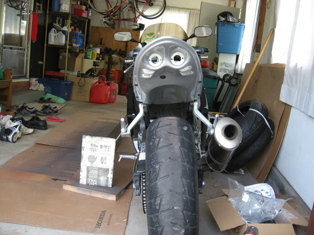
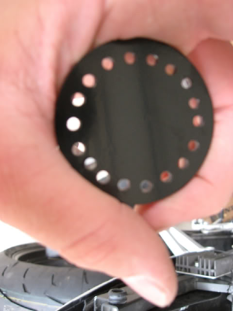
Okay sorry this is taking so long but heres where I am.
how the undertail was when I got it (note: only two holes for each devil eye for the studs to go through)
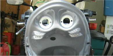
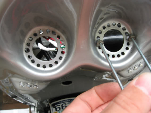
I drilled out a hole for each led to poke through into my plex
The painted plex that will be holding the leds
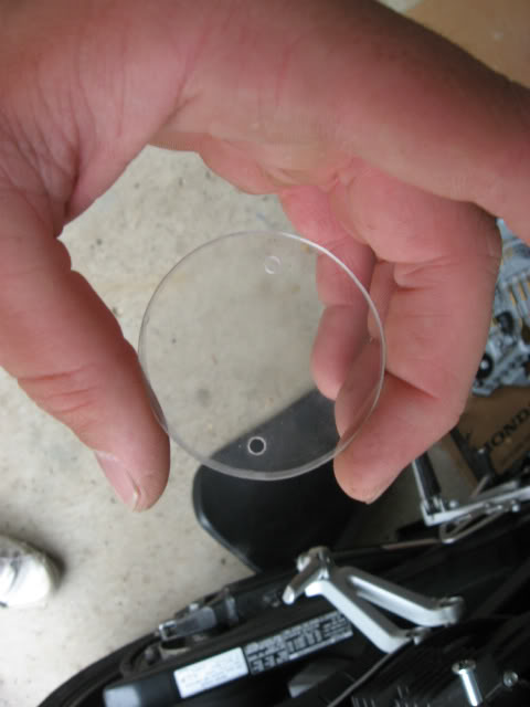
The clear plex that will be covering the tips of the leds
how the undertail was when I got it (note: only two holes for each devil eye for the studs to go through)
I drilled out a hole for each led to poke through into my plex
The painted plex that will be holding the leds
The clear plex that will be covering the tips of the leds
#45
07-11-2011, 02:14 PM
Member
Join Date: Apr 2010
Location: Reno, NV
Posts: 65
Likes: 0
Received 0 Likes
on
0 Posts

#46
07-11-2011, 03:28 PM
Join Date: Mar 2011
Posts: 296
Likes: 0
Received 0 Likes
on
0 Posts
Yeah I've been getting my wires in and I had to drill each "led holder" (the black plex) to hold 8 5mm LEDs for brakes. I wanted to have separate lights illuminate for the brakes so that way there was no question for cage drivers when my brakes were on (versus using the same lights for running and brake lights, the only difference being brightness). I'm sure I worded that whole statement terribly.
I'm hoping to have this biatch on the road tomorrow. I WANT TO RIDE ITS RIDICULOUS. I've been freaking out lately, getting more irritated with people more easily because I haven't been getting my riding fix. It sucks.
More on topic with this thread: The current wiring situation is a disaster. Its so damn messy I want to throw up. I probably should have a circuit board on the other side of the LEDs to reduce some wiring ugliness. Maybe in the winter I'll redo everything and make it cleaner (and make a new LED pattern...I have sexy ideas ). I was thinking about making the brake lights strobe three times every time I hit the brakes. What is the part called that makes them strobe?
I'm hoping to have this biatch on the road tomorrow. I WANT TO RIDE ITS RIDICULOUS. I've been freaking out lately, getting more irritated with people more easily because I haven't been getting my riding fix. It sucks.
More on topic with this thread: The current wiring situation is a disaster. Its so damn messy I want to throw up. I probably should have a circuit board on the other side of the LEDs to reduce some wiring ugliness. Maybe in the winter I'll redo everything and make it cleaner (and make a new LED pattern...I have sexy ideas
). I was thinking about making the brake lights strobe three times every time I hit the brakes. What is the part called that makes them strobe?
#47
07-12-2011, 12:44 AM

Senior Member
Wow... didn't read this whole thing but based on the original post's question, complex, though certainly doable.
If I were attempting it, I would be to use a programmable IC chips with as many outputs as I needed for 1 light. This way I could code in the order and duration of each LED "event" and make it work repeatably and reliably. As I said I would use an IC chip per side (so in the case of the original poster wanting a left and a right... 2 ICs), plus a 3rd master IC to control the multiple functions (brake, turn signal, emergency, etc.). This way the "light IC" is simply a "light controller" and ONLY is used for LED timing. The master IC is used to turn the "light IC" on and off as desired for different lighting functions.
Cool idea though!

Thread
Thread Starter
Forum
Replies
Last Post