
electrical components
#11
 06-21-2011, 11:06 AM


Member
Join Date: Apr 2010
Location: Reno, NV
Posts: 65
Likes: 0
Received 0 Likes
on
0 Posts
I got them from superbrightleds.com They are the 3mm red ones, here is what they give for specs
3mm LED RL3-R5030 Specifications
3mm LED RL3-R5030 Specifications
stupid me, the LEDs I bought weren't for 12v power. I can just put a resistor in and it will be okay though, right? (for series, parallel would need a resistor on every bulb yes?) Should I pick up a handful of 470 ohm resistors?
#12
06-23-2011, 08:12 AM
Join Date: Mar 2011
Posts: 296
Likes: 0
Received 0 Likes
on
0 Posts
#13
06-23-2011, 01:11 PM
Join Date: Mar 2011
Posts: 296
Likes: 0
Received 0 Likes
on
0 Posts
Sooo I got my superbright leds today. I mistook 3mm leds for 5mm, so now I have a bunch of tiny *** leds. That's okay though, each ring will look "high def". I can fit 21-22 leds in a ring (I'm calling each devil eye a ring). My only concern is brightness. I took 2 AA batteries out of my camera to see how bright they are. When I use one battery its SUPER dim (1.5v). But when I use two batteries in series (I know, that's past the 2.6v rating) its SUPER bright (this was in my room, so my definition of SUPER bright probably translates to reasonably acceptable for road use). Should I see how they look at 2.1 ish volts? Just ghetto rig some batteries and resistors and get my voltage and current right to see how bright they are before we continue?
#14
06-23-2011, 03:35 PM
Join Date: Mar 2011
Posts: 296
Likes: 0
Received 0 Likes
on
0 Posts
#15
06-23-2011, 06:22 PM
Member
Join Date: Apr 2010
Location: Reno, NV
Posts: 65
Likes: 0
Received 0 Likes
on
0 Posts
Yes, running the LEDs at the right voltage and current will give you a much better feel for how bright they will be. Run them at 2.4V, 20mA (2.5v is the max voltage and the max operating current is 20mA). That will give them a good lifetime and still be very close to as bright as they will go.
Snap some pics of the undertail and taillights and post em up so I have an idea of what you're working with and how you plan on mounting the LEDs. Speaking of that, how do you plan to mount the LEDs?
Edit: you say you can fit 21-22 LEDs in each ring. With 21 Leds in each ring, the current draw when they are all on would be 21*0.02=0.42 Amps. That means two things. 1) You MAY NOT need to upgrade your wiring. As long as the wiring is AWG 30 or larger, it will work just fine. 2) You should check what kind of heat those LEDs produce. Too much heat in a small taillight assembly can cause some problems; in particular, reducing the brightness of the LEDs (as LEDs get hotter, they become less bright).
Edit: I was just going to start up a schematic for you, and thought of a couple things. One, since you want the taillights to be symmetric, and "come on" symmetrically, we can simplify the circuitry and have each transistor (used as a switch in this case) turn on one LED from each taillight (total of 2 LEDs wired in series with each transistor). For example, when both the 12:00 LEDs (take a ring of 12 for simplicity in this example, each hour on a clock represents an individual LED) are to be turned on, a single transistor can be used to switch them on. We would have the corresponding LEDs from each taillight wired in series (12:00 LEDs are wired in series to a single transistor, as are the 11:00 LEDs, and so on and so forth).
Second, the more LEDs you want in each taillight, the more complicated the counter circuit and multiplexer must be, as well as the more flip-flops you need. For 21 LEDs in each taillight, you would need a 6 bit counter to have enough combinations to activate all of the transistors. For 12 LEDs per taillight, you would need a 5 bit counter. Not sure on a price difference between these, I just wanted you to know that the circuitry will be more complicated the more LEDs you want.
Last edited by monsterjeepn; 06-23-2011 at 07:19 PM.
#16
06-23-2011, 08:07 PM
Join Date: Mar 2011
Posts: 296
Likes: 0
Received 0 Likes
on
0 Posts
#17
06-23-2011, 10:28 PM
Member
Join Date: Apr 2010
Location: Reno, NV
Posts: 65
Likes: 0
Received 0 Likes
on
0 Posts
#18
06-23-2011, 11:06 PM
Join Date: Mar 2011
Posts: 296
Likes: 0
Received 0 Likes
on
0 Posts
#19
06-24-2011, 11:47 AM
Member
Join Date: Apr 2010
Location: Reno, NV
Posts: 65
Likes: 0
Received 0 Likes
on
0 Posts
Oh I gotcha. I found it. That is actually very similar to what I was looking at (I have an '04) when I was shopping for an undertail on mine. I heard to many bad things about the brake light/blinker brightness on aftermarket undertails, so I decided to get a hotbodies undertail to allow me to keep my stock brake light.
I was going to start up a schematic for you yesterday, but had a few issues with my computer, so I'll have to do some work on it this weekend. PICS! PICS! PICS!
I was going to start up a schematic for you yesterday, but had a few issues with my computer, so I'll have to do some work on it this weekend.
#20
06-24-2011, 05:22 PM
Join Date: Mar 2011
Posts: 296
Likes: 0
Received 0 Likes
on
0 Posts
NOW NOW NOW!!!
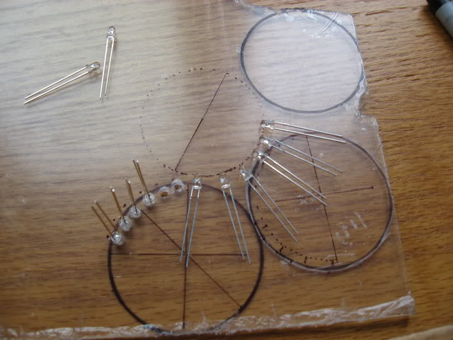
several failed drawings of circles and junk
the undertail (minus ugly *** tail lights)
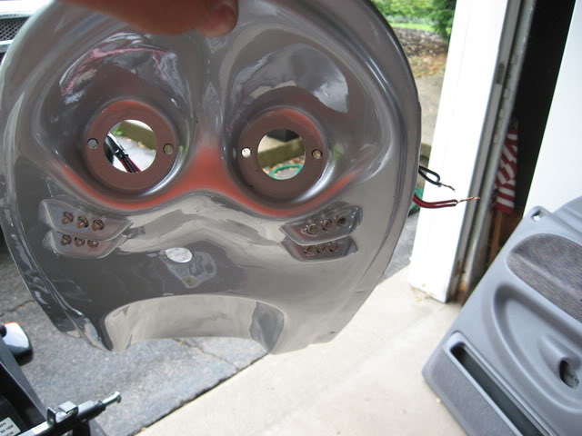
The disgusting projectors they tried to pass off as tail lights
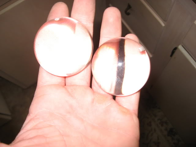
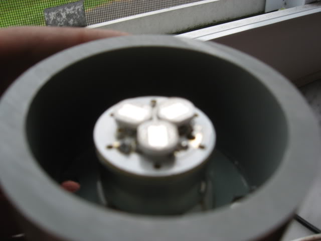
The actual light part (yes, the grey stuff is pvc drain pipe...like the stuff in your house)
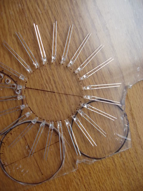
To give you an idea of how these will look...(I'm drilling holes tomorrow based on this spacing)
several failed drawings of circles and junk
the undertail (minus ugly *** tail lights)
The disgusting projectors they tried to pass off as tail lights
The actual light part (yes, the grey stuff is pvc drain pipe...like the stuff in your house)
To give you an idea of how these will look...(I'm drilling holes tomorrow based on this spacing)
Last edited by Honda125 358; 06-24-2011 at 08:56 PM.