F4i Front Intake Signals
#11
 10-03-2007, 08:03 PM


#12
10-04-2007, 12:06 AM

Join Date: Oct 2005
Location:
Posts: 792
Likes: 0
Received 0 Likes
on
0 Posts
this is what a resistor generally looks like:

you can solder it anywhere between the positive and negative ends of the signals. on mine it is soldered in the middle of the negative wire and covered by the sleeving i used:
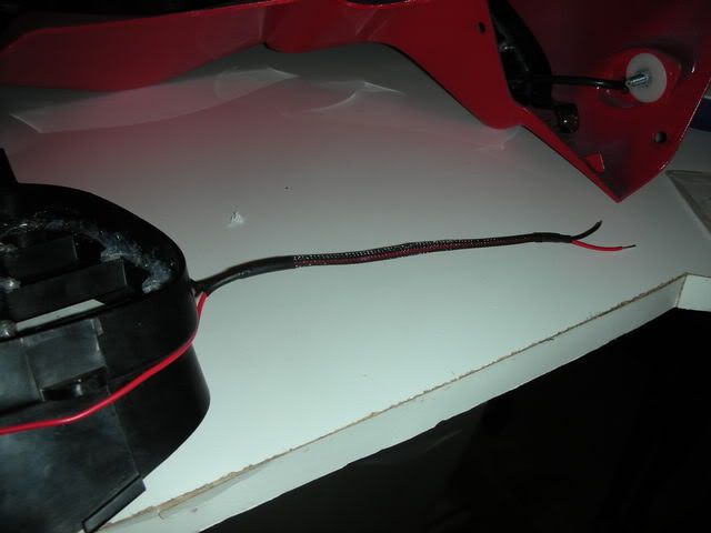
its right in the middle, so small you can't even see it with the sleeving over it. but you can solder it between any LED or between the end of the wire from the signal to the harness. as long as its somewhere in the loop it will work. you can use a 1/4 watt resistor, but the ohm value will be different depending on the amount of LEDs you use, the voltage drop of the LEDs, the mA they run at, and the volts that you bike puts out. does that help?
you can solder it anywhere between the positive and negative ends of the signals. on mine it is soldered in the middle of the negative wire and covered by the sleeving i used:
its right in the middle, so small you can't even see it with the sleeving over it. but you can solder it between any LED or between the end of the wire from the signal to the harness. as long as its somewhere in the loop it will work. you can use a 1/4 watt resistor, but the ohm value will be different depending on the amount of LEDs you use, the voltage drop of the LEDs, the mA they run at, and the volts that you bike puts out. does that help?
Last edited by axsys; 12-18-2014 at 09:09 AM.
#13
10-06-2007, 10:55 AM

Join Date: Apr 2007
Location: FT. IRWIN, CA
Posts: 72
Likes: 0
Received 0 Likes
on
0 Posts
#14
10-06-2007, 01:15 PM
Join Date: Oct 2005
Location:
Posts: 792
Likes: 0
Received 0 Likes
on
0 Posts

Thread
Thread Starter
Forum
Replies
Last Post
Lowridese
F4i - Main Forum
16
05-01-2010 01:12 AM