F4i Front Intake Signals
#1
 09-19-2007, 05:52 PM


Join Date: Oct 2005
Location:
Posts: 792
Likes: 0
Received 0 Likes
on
0 Posts
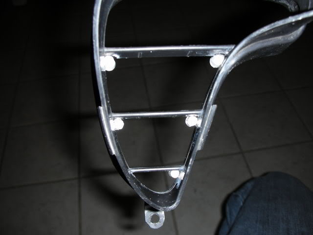
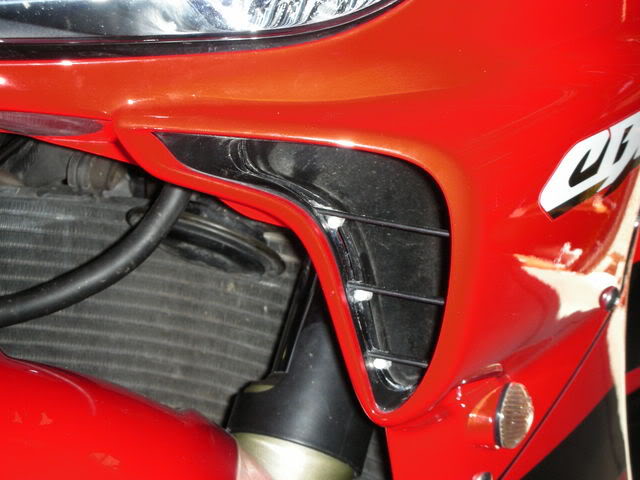
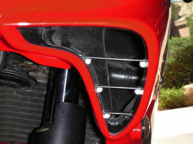
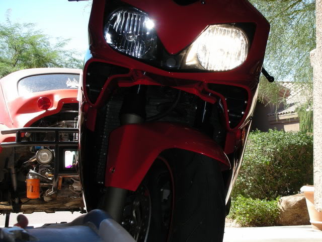
So anyone with the Hotbodies front flushmounts knows that the signals are a little hard to see from the front of the bike. Well, instead of buying some stalked signals to make them easier to see, I decided to add some LEDs to theair intakes on the front of the bike.
Required Materials:
-LEDs
-Resistors
-Glue
-Wire
-Solder
-Heatshrink
Required Tools:
-5mm Allen Wrench and Phillips Screwdriver (Remove fairings)
-Wire Cutters/Strippers
-Soldering Iron
-Lighter/Heat Gun
-Needle Nosed Pliers
DISCLAIMER - This is just a guide. I am not responsible for any damage you do to your bike. This project requires gluing, drilling, and soldering. If you do not feel comfortable doing any of those, then do not try this on your bike.
Start by removing the front fairing. You can keep the headlight and windscreen on, just take off the ram air covers, the 3 allen bolts on each side, and the 2 phillips rivets underneath. Pull the front of the bike off, making sure to unplug the headlight connector. Now remove the Front intake grills. There is 2 phillips screws holding each one in.
Now we start to have some fun. Start thinking about where you want to mount each LED. I only had 10 LEDs left from my last project, so I chose to put 5 on each side. Here is one thing to think about though. The LEDs I used drop about 2.4 volts. My bike puts out just over 14v when running. Therefore, I can only have 5 LEDs in a series. If I had, say 8 LEDs, I would need to run 2 series of 4 LEDs. More series means more wires you have to run. You can use this resistor calculator to find out how many you can run in a series (make sure to use the "Leds in series" one): LED Resistor Calculator. Be creative, you don't have to put yours exactly where I put mine! I decided to go with these LEDs: eBay 5mm Amber LEDs 25k mcd
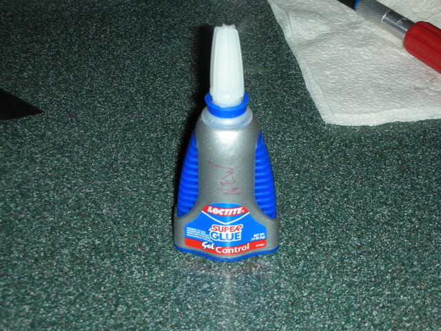
So, once you pick how many LEDs you want to use, you can start putting them where you want them. I used some Loctite Super Glue Gel to glue mine into place. It takes a while to dry, but its pretty damn strong. It did however create some difficulties for me though, which I will talk about later.
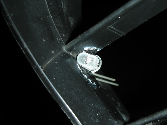
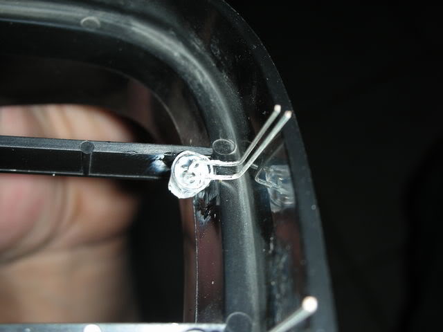
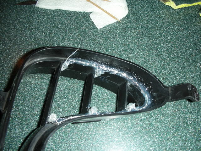
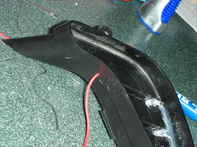
Start gluing the LEDs in, paying close attention to which way the legs are facing. You want to have them parallel to the edge of the grill, as well as having them orientated correctly for polarity. You can see that each LED has a long leg and a short leg. When running in series, the long leg of one LED will always connect to the short leg of another LED. I would also keep the legs straight while you are gluing them and bend them when they are dry. I found this much easier to do rather than bending and then trying to glue.
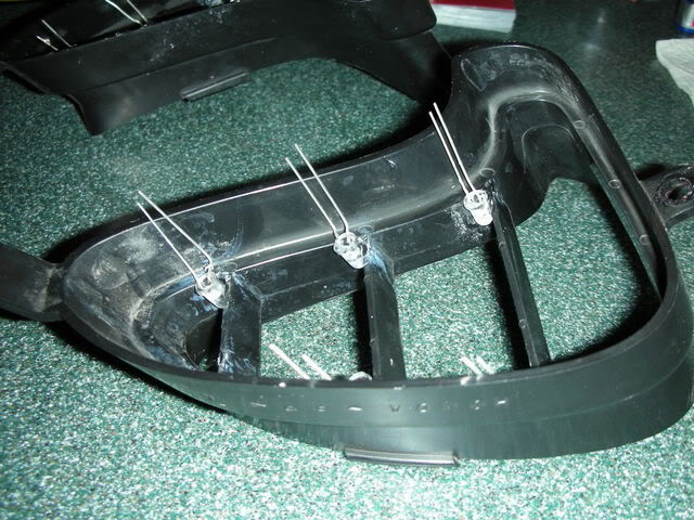
Make sure that they line up straight underneath the little shelf on the grill.
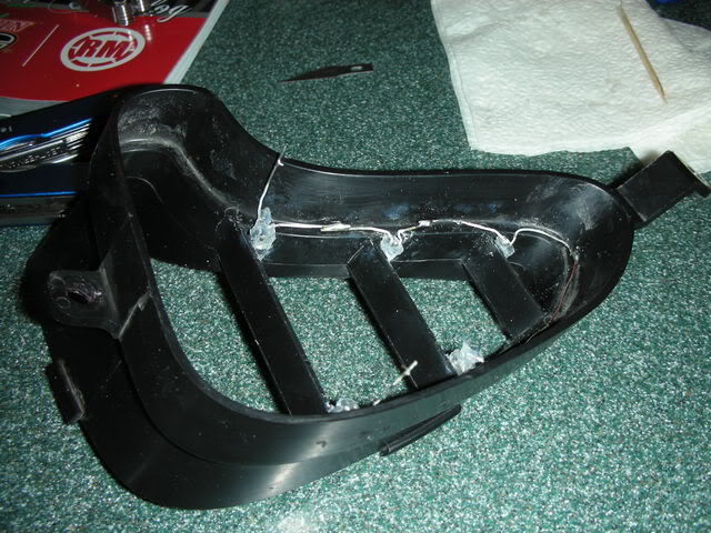
Once they are all glued in, let it dry overnight. Once they are dry, we are ready to solder them all together. However, first I had to fix the problem my superglue caused. If you look at this picture, you can see some white spots all over the plastic. The chemicals in the glue evaporated and left this around everywhere that I had glued. So I cut up a green kitchen scrubber and scrubbed most of it away. It was pretty easy.
[IMG]http://i71.ph
________
BDSM BONDAGE
Required Materials:
-LEDs
-Resistors
-Glue
-Wire
-Solder
-Heatshrink
Required Tools:
-5mm Allen Wrench and Phillips Screwdriver (Remove fairings)
-Wire Cutters/Strippers
-Soldering Iron
-Lighter/Heat Gun
-Needle Nosed Pliers
DISCLAIMER - This is just a guide. I am not responsible for any damage you do to your bike. This project requires gluing, drilling, and soldering. If you do not feel comfortable doing any of those, then do not try this on your bike.
Start by removing the front fairing. You can keep the headlight and windscreen on, just take off the ram air covers, the 3 allen bolts on each side, and the 2 phillips rivets underneath. Pull the front of the bike off, making sure to unplug the headlight connector. Now remove the Front intake grills. There is 2 phillips screws holding each one in.
Now we start to have some fun. Start thinking about where you want to mount each LED. I only had 10 LEDs left from my last project, so I chose to put 5 on each side. Here is one thing to think about though. The LEDs I used drop about 2.4 volts. My bike puts out just over 14v when running. Therefore, I can only have 5 LEDs in a series. If I had, say 8 LEDs, I would need to run 2 series of 4 LEDs. More series means more wires you have to run. You can use this resistor calculator to find out how many you can run in a series (make sure to use the "Leds in series" one): LED Resistor Calculator. Be creative, you don't have to put yours exactly where I put mine! I decided to go with these LEDs: eBay 5mm Amber LEDs 25k mcd
So, once you pick how many LEDs you want to use, you can start putting them where you want them. I used some Loctite Super Glue Gel to glue mine into place. It takes a while to dry, but its pretty damn strong. It did however create some difficulties for me though, which I will talk about later.
Start gluing the LEDs in, paying close attention to which way the legs are facing. You want to have them parallel to the edge of the grill, as well as having them orientated correctly for polarity. You can see that each LED has a long leg and a short leg. When running in series, the long leg of one LED will always connect to the short leg of another LED. I would also keep the legs straight while you are gluing them and bend them when they are dry. I found this much easier to do rather than bending and then trying to glue.
Make sure that they line up straight underneath the little shelf on the grill.
Once they are all glued in, let it dry overnight. Once they are dry, we are ready to solder them all together. However, first I had to fix the problem my superglue caused. If you look at this picture, you can see some white spots all over the plastic. The chemicals in the glue evaporated and left this around everywhere that I had glued. So I cut up a green kitchen scrubber and scrubbed most of it away. It was pretty easy.
[IMG]http://i71.ph
________
BDSM BONDAGE
Last edited by axsys; 05-04-2011 at 11:03 PM.
#2
09-19-2007, 07:07 PM
Join Date: Oct 2005
Location:
Posts: 792
Likes: 0
Received 0 Likes
on
0 Posts
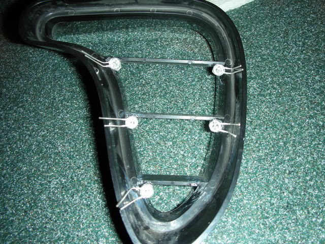
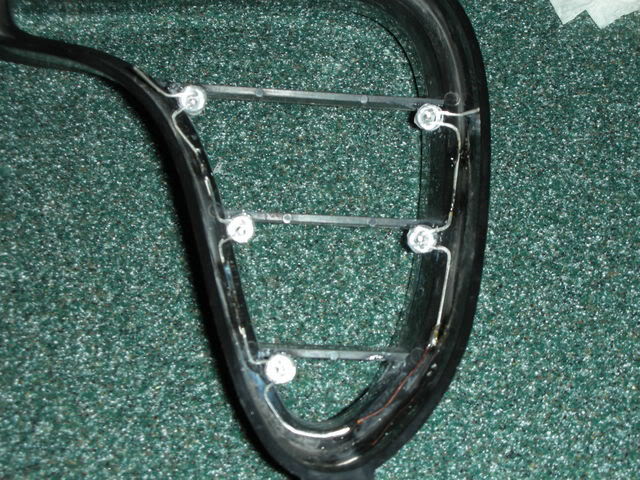
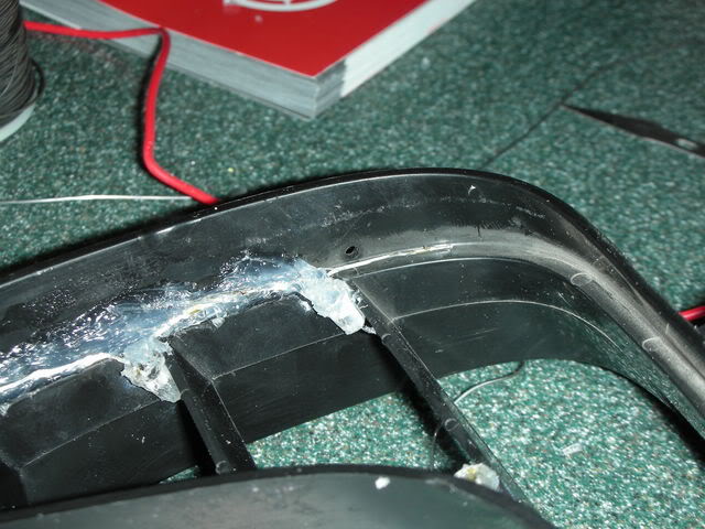
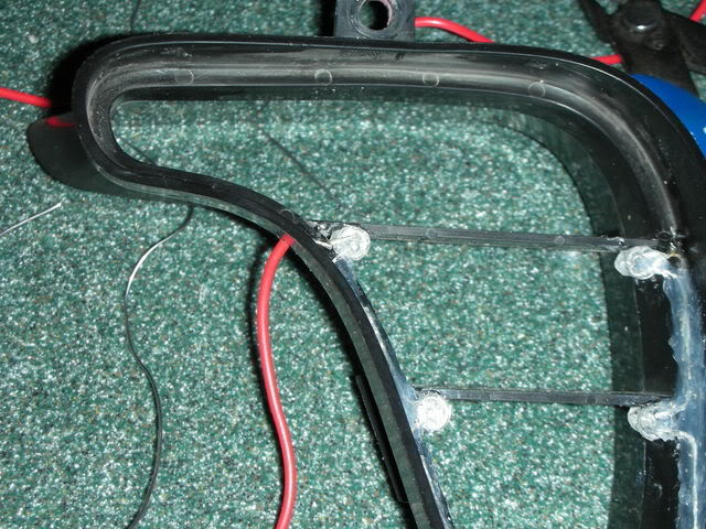
So now it was time to start soldering. Using some needle nosed pliers, I carefully and slowly bent the legs of the LEDs so that they would fold onto the edge of the grill and then fold onto each other. Then just add a little bit of solder to each joint. Don't forget that with LEDs, you can't keep heat on the legs for too long, so try to get it done as quickly as you can.
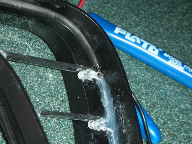
I had to add a small piece of wire where the legs weren't long enough to reach each other.
After trimming the legs so that they ended where the solder joint was, I put some silicone over any of the wires to waterproof it. his stuff is pretty sticky, so wear a rubber glove when applying it.
While thats drying, I put 2 holes into each grill for the main wires to com out of. You can use a dremel, a drill, or a knife if you have to. You just need a hole big enough for the wire to go through.
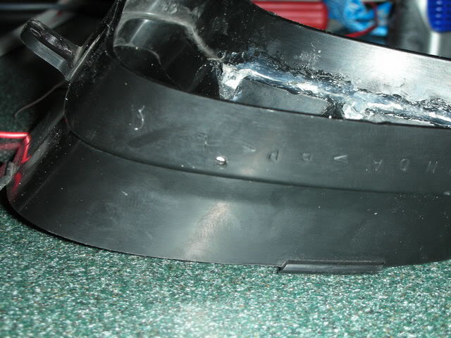
Now take some good 16 gauge or so stranded wire, strip the end, and stick it through the hole. Add some solder, trim it, and then put some more silicone over it.
More to come soon!
________
FERRARI F2004 HISTORY
I had to add a small piece of wire where the legs weren't long enough to reach each other.
After trimming the legs so that they ended where the solder joint was, I put some silicone over any of the wires to waterproof it. his stuff is pretty sticky, so wear a rubber glove when applying it.
While thats drying, I put 2 holes into each grill for the main wires to com out of. You can use a dremel, a drill, or a knife if you have to. You just need a hole big enough for the wire to go through.
Now take some good 16 gauge or so stranded wire, strip the end, and stick it through the hole. Add some solder, trim it, and then put some more silicone over it.
More to come soon!
________
FERRARI F2004 HISTORY
Last edited by axsys; 05-04-2011 at 11:03 PM.
#3
09-19-2007, 11:23 PM

Senior Member
Join Date: Sep 2007
Location:
Posts: 197
Likes: 0
Received 0 Likes
on
0 Posts

#5
09-20-2007, 01:42 PM
Join Date: Oct 2005
Location:
Posts: 792
Likes: 0
Received 0 Likes
on
0 Posts
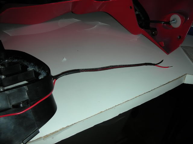
So now its time to install everything onto the bike. If you want, you can get a little fancy and put some sleeving over your wires like I did:
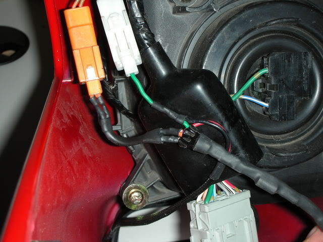
Screw the grills back in with the 2 phillips screws for each one. So what we need to do is splice into the wiring harness to attach the signals. You are looking for the White and Orange connectors on the left side of the headlight. The right side has White and Blue connectors that are identical to the left, just Blue instead of Orange. For this guide, I am just going to show how to wire the left side, as the right side is the same except for the color. Now, there are 3 wires here - the Green wire in the White connector, an Orange wire in the Orange connector, and another Orange with white stripe wire in the Orange connector. We need to solder the black (-) wire from our LEDs to the Green wire, and the red (+) wire to the solid Orange wire. So thats Black to Green, Red to solid Orange (solid Blue for right side).
The way I did this was to cut the wires after the connector on the turn signals, then solder them back together as well as soldering my new wire inline with them:
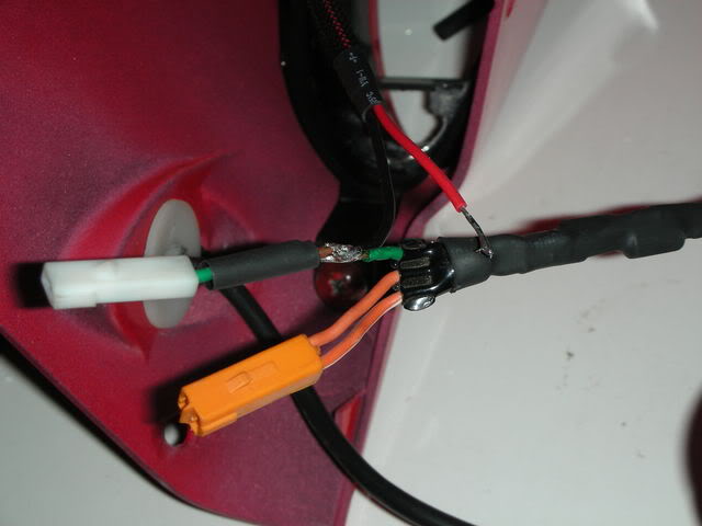
It's a little hard to see the black wire in the photo, but its soldered to that joint as well as the green wires. Make sure to put some heatshrink or electrical tape over the connection when done. Now, do the same for the solid orange wire. I had a problem with the wire being a little too short to fit heatshrink over (I prefer not to use electrical tape, but it should work fine if you do), so I added a little extra wire in there to give me some more room to work with. When finished, it turned out like this:
As you can see, the Red to solid Orange, Black to Green. And thats it! Do the other side, then put your bike back together and enjoy your hard work!
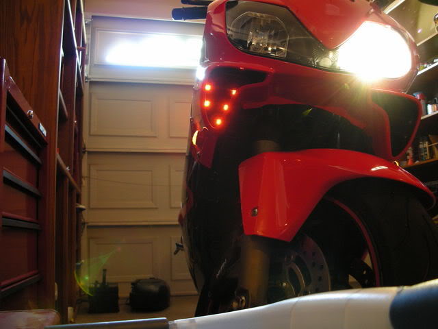
I kind of rushed through the How-To a little bit, so if you guys feel like I was a little vague in some areas, let me know and I can be more clear. I will also post some videos up later tonight. Good luck!
________
Confucianism Forums
Screw the grills back in with the 2 phillips screws for each one. So what we need to do is splice into the wiring harness to attach the signals. You are looking for the White and Orange connectors on the left side of the headlight. The right side has White and Blue connectors that are identical to the left, just Blue instead of Orange. For this guide, I am just going to show how to wire the left side, as the right side is the same except for the color. Now, there are 3 wires here - the Green wire in the White connector, an Orange wire in the Orange connector, and another Orange with white stripe wire in the Orange connector. We need to solder the black (-) wire from our LEDs to the Green wire, and the red (+) wire to the solid Orange wire. So thats Black to Green, Red to solid Orange (solid Blue for right side).
The way I did this was to cut the wires after the connector on the turn signals, then solder them back together as well as soldering my new wire inline with them:
It's a little hard to see the black wire in the photo, but its soldered to that joint as well as the green wires. Make sure to put some heatshrink or electrical tape over the connection when done. Now, do the same for the solid orange wire. I had a problem with the wire being a little too short to fit heatshrink over (I prefer not to use electrical tape, but it should work fine if you do), so I added a little extra wire in there to give me some more room to work with. When finished, it turned out like this:
As you can see, the Red to solid Orange, Black to Green. And thats it! Do the other side, then put your bike back together and enjoy your hard work!
I kind of rushed through the How-To a little bit, so if you guys feel like I was a little vague in some areas, let me know and I can be more clear. I will also post some videos up later tonight. Good luck!
________
Confucianism Forums
Last edited by axsys; 05-04-2011 at 11:04 PM.
#6
09-20-2007, 01:55 PM

Senior Member
Join Date: Jul 2007
Location:
Posts: 151
Likes: 0
Received 0 Likes
on
0 Posts
 .
.
#7
09-20-2007, 02:10 PM

did the LED's you used have built in resistors? or did u just not add any at all? Hows the flash rate with them added in? I havent been able to see any of your videos, opens up but no picture. i dont have those fancy programs.
Also, I think im gonna try to use 1minepoxy rather than superglue. I trust it to hold alittle better.
VERY NICE JOB BTW !!!
Oh and is there really a big difference in intensity/brightness between say 13k-15k mcd and 25k mcd?? Sounds like there would be, but ive been told otherwise and I have been searching for side by side comparison pix but have no luck....
#8
09-20-2007, 04:03 PM
Join Date: Oct 2005
Location:
Posts: 792
Likes: 0
Received 0 Likes
on
0 Posts
scattabrain, im glad you like the how-to. if you get some LEDs locally, make sure they are really bright. i know radioshack sells leds, but they are really dim, like around 1000mcd vs. the 25000mcd i used. if you plan on ordering some, i would recommend the ebay store i bought them from. they take like 1-2 weeks to get here, but they are cheap and really bright.
06CBRF4i, i dont have a single load resistor on my bike, every signal is made out of leds, and its the stock flash rate. how you ask? i bought an electronic flasher relays off of ebay. you simply unplug your old relay and plug this one in. you dont need any of those huge resistors anywhere. 1 minute epoxy would work pretty good, i just had that glue laying around so i used it. as far as led intensity, i dont think it would be too much of a difference between 15k and 25k. i would hook a few up to a 9 volts battery (making sure to use the correct resistors of course) and see if you think they are bright enough. you could always add more LEDs than i did, which would probably make up for the lower intensity.
oh, and ill have some videos on youtube later tonight so there is no more problems with the whole codec thing.....
________
The cigar boss
Last edited by axsys; 05-04-2011 at 11:04 PM.
#9
10-02-2007, 11:37 PM

Just to make sure I am correct on everything before I jump into this. On the leds the short post is going to be the ground and the long post the hot? Also you said in items need something about a resistor but I did not see anything about that in the how to... Do you have to run on? I am ordering the same leds as you but I am on running 4 in my pegs. Thanks - dAb
#10
10-03-2007, 01:21 AM
Join Date: Oct 2005
Location:
Posts: 792
Likes: 0
Received 0 Likes
on
0 Posts
ORIGINAL: dab_f4i
Just to make sure I am correct on everything before I jump into this. On the leds the short post is going to be the ground and the long post the hot? Also you said in items need something about a resistor but I did not see anything about that in the how to... Do you have to run on? I am ordering the same leds as you but I am on running 4 in my pegs. Thanks - dAb
Just to make sure I am correct on everything before I jump into this. On the leds the short post is going to be the ground and the long post the hot? Also you said in items need something about a resistor but I did not see anything about that in the how to... Do you have to run on? I am ordering the same leds as you but I am on running 4 in my pegs. Thanks - dAb
As for the resistors, you need some regular current resistors. These cost about a dollar for a pack of five at RadioShack. And yes, you HAVE to run them anytime you wire LEDs to something. If you need help figuring out which resistors to buy, feel free to shoot me a PM. But just so you know, these resistors are just current resistors to keep the right amplitude for the LEDs, they are not load resistors to keep your turn signals flashing at the stock rate.
Last edited by axsys; 12-18-2014 at 09:08 AM.