
2002 CBR 954RR no spark on any plugs
#11
 03-17-2024, 08:15 PM


Have an 03 954 that was wrecked. I�ve jumped the green white to ground. 12v at all coils and injectors. Crank pulse is 1v. Cam pulse regularly bounces around and hits .8-.9 every few seconds.
fuel pump kicks on for 3 seconds. Pink wire is 8.9v at the switch but it�s 10.3 at the gray connector.
what am I missing??
fuel pump kicks on for 3 seconds. Pink wire is 8.9v at the switch but it�s 10.3 at the gray connector.
what am I missing??
#12
03-17-2024, 08:34 PM

Senior Member
First, make sure MAP & TPS connectors arent reversed.
Also measure resistance of grn/red wire to chassis-ground at lt.gr ECU connector.
Sorry, I reviewed posts and if ECU primes pump, then it’s happy with pink wire. So we chased red herring there. Not sure why you would measure higher voltage at destination on pink wire than at ign-switch though. Was this measured with ECU disconnected? This might point to wiring issue.
Next is to test for grounding pulses from ECU to injectors and coils. Try using dual-color LED test-light on injector/coil connector. Clamp cable of test-probe to battery +pos terminal (we’re measuring for ground signal). Then probe non-power terminal of injector/coil connectors (the other one next to blk/wht power terminal). Crank engine, does tester blink green for grounding?
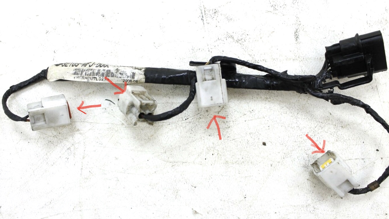
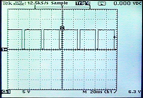
Due to short interval of injector & coil pulses, blink on test-light may not be long enough for human eyes to see. Solenoid light would be better as it has duration-extending circuitry to keep light lit over 100ms for human eyes to see. Oscilloscope can also be used to probe injector/coil wires. Looks like this, high most of time with short drops to ground to fire injectors & coils.
Also measure resistance of grn/red wire to chassis-ground at lt.gr ECU connector.
Sorry, I reviewed posts and if ECU primes pump, then it’s happy with pink wire. So we chased red herring there. Not sure why you would measure higher voltage at destination on pink wire than at ign-switch though. Was this measured with ECU disconnected? This might point to wiring issue.
Next is to test for grounding pulses from ECU to injectors and coils. Try using dual-color LED test-light on injector/coil connector. Clamp cable of test-probe to battery +pos terminal (we’re measuring for ground signal). Then probe non-power terminal of injector/coil connectors (the other one next to blk/wht power terminal). Crank engine, does tester blink green for grounding?
Due to short interval of injector & coil pulses, blink on test-light may not be long enough for human eyes to see. Solenoid light would be better as it has duration-extending circuitry to keep light lit over 100ms for human eyes to see. Oscilloscope can also be used to probe injector/coil wires. Looks like this, high most of time with short drops to ground to fire injectors & coils.
Last edited by dannoxyz; 03-17-2024 at 08:56 PM.
#16
03-17-2024, 10:25 PM
Senior Member
Test with manually grounding grn/red wire at lt.gr ECU connector as well.
Lack of injector/coil trigger pulses can be CMP/CKP timing issue. Did you measure these at sensors themselves or at ECU connector?
Lack of injector/coil trigger pulses can be CMP/CKP timing issue. Did you measure these at sensors themselves or at ECU connector?
#20
03-18-2024, 02:41 PM
Senior Member
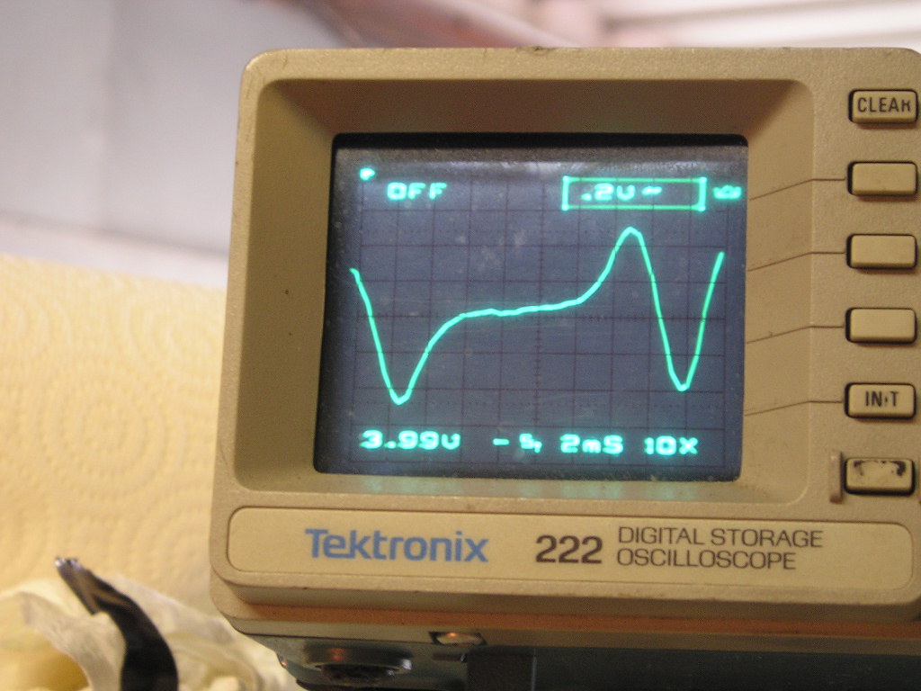
That's OK, should be minimum of 0,7v for pickups I think.
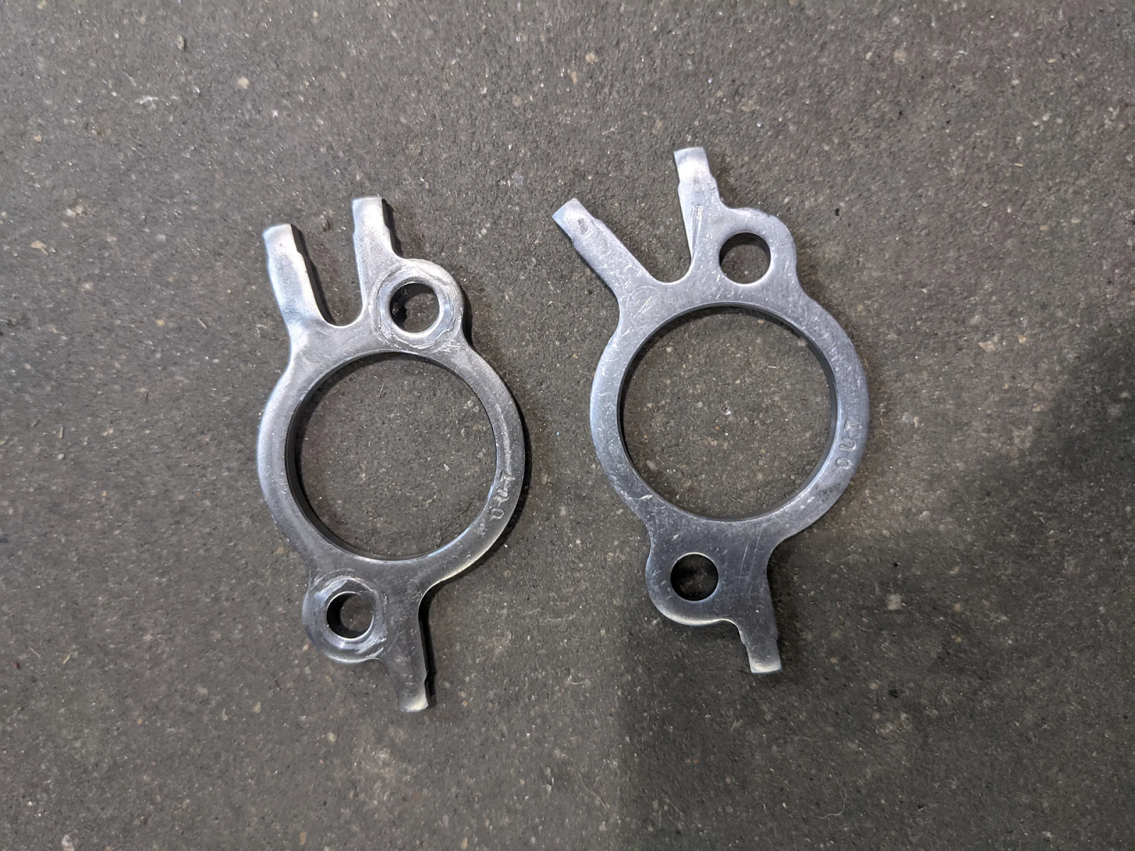
More important is their timing. Very common to have cam-sensor trigger wheel bent when removing for valve-adjustment. Take look at yours and make sure it matches one on right.
Other possibility is if sensor wires have been repaired or replaced, they may possibly be reversed. This causes waveform to start on negative-slope instead of positive one. ECU won't see signal.