No Power to Coils - 99' CBR F4 600
#21
 03-08-2024, 01:44 PM


I understand that you don't have much experience with a multi-meter, but this is where its going to be extremely important that we have the exact information. the number you provided of .482 (half an ohm) would mean that your pick-up coil is bad. if it measured 482 (four hundred), then it would be good. what setting did you have your multi-meter on (1k, 10k 100k)?
#22
03-08-2024, 01:53 PM
Meaning that my pickup coil is good so now i have to search for another answer to this no spark situation. I dont suspect that dreaded pink wire im forcing 8.9V through it with the DC Converter and i know it arrived to the icm. But should i double check it and install the fuel pump and see if it primes?
#23
03-08-2024, 02:02 PM

Senior Member
Sure try and see if there’s pump prime.
Also verify safety-interloc status:
1. Disconnect ignitor, gear box in neutral, clutch squeezed OR kickstand up. Measure at ignitor connector
2. Measure resistance between grn/wht wire terminal and chassis earth, ohms=??
3. Measure resistance between grn/red wire terminal and chassis earth, ohms=??
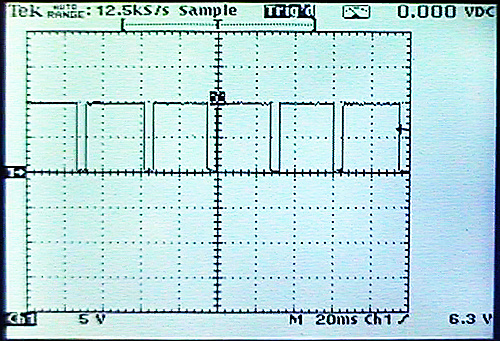
If safety-interloc isn’t working, you’ll get fuel-pull prime and cranking, but no spark-trigger signal from ignitor. Trigger line between ignitor & coils should look like this on oscilloscope. Battery voltage most of time with short intervals of zero as ignitor earths line to trigger spark.
Also verify safety-interloc status:
1. Disconnect ignitor, gear box in neutral, clutch squeezed OR kickstand up. Measure at ignitor connector
2. Measure resistance between grn/wht wire terminal and chassis earth, ohms=??
3. Measure resistance between grn/red wire terminal and chassis earth, ohms=??
If safety-interloc isn’t working, you’ll get fuel-pull prime and cranking, but no spark-trigger signal from ignitor. Trigger line between ignitor & coils should look like this on oscilloscope. Battery voltage most of time with short intervals of zero as ignitor earths line to trigger spark.
Last edited by dannoxyz; 03-08-2024 at 02:04 PM.
#24
03-08-2024, 11:12 PM
Sure try and see if there�s pump prime.
Also verify safety-interloc status:
1. Disconnect ignitor, gear box in neutral, clutch squeezed OR kickstand up. Measure at ignitor connector
2. Measure resistance between grn/wht wire terminal and chassis earth, ohms=??
3. Measure resistance between grn/red wire terminal and chassis earth, ohms=??
If safety-interloc isn�t working, you�ll get fuel-pull prime and cranking, but no spark-trigger signal from ignitor. Trigger line between ignitor & coils should look like this on oscilloscope. Battery voltage most of time with short intervals of zero as ignitor earths line to trigger spark.
9vdc to icm is good since there would be a prime
- Grn/wht 1.326 M Ohms


#25
03-09-2024, 10:54 AM
Senior Member
Ok, grn/red only goes to starter-solenoid. That’s fine.
Pump relay only runs when engine is spinning. Or more correctly, it’s triggered by ignition pulses by ignitor. So no way to determine if fuel-pump relay is operational until you get sparks working.
grn/wht must be connected to earth by safety switches (0 ohms). Ignitor will not trigger coils until then.
Last edited by dannoxyz; 03-09-2024 at 10:58 AM.
#26
03-09-2024, 10:58 AM
Ok, grn/red only goes to starter-solenoid. That�s fine.
Pump relay only runs when engine is spinning. Or more correct, it�s triggered by ignition pulses by ignitor. So no way to determine if fuel-pump relay is operational until you get sparks working.
grn/wht must be connected to earth by safety switches (0 ohms). Ignitor will not trigger coils until then.
#27
03-09-2024, 11:23 AM
#28
03-09-2024, 11:58 AM
Alrighty i see now where it is ACTUALLY going into the kickstand grn/wht supposed to be O/L if the stand is down i checked a ground where many green wires are going into and glanced over the one around the radiator fan they seem clean but i cleaned the one on the chassis as i saw a bit of corrosion nothing crazy just a small bit of green. I dont think the kickstand stops the ignitor from kicking spark however.
#29
03-09-2024, 01:26 PM
Senior Member
What happens when you stop with clutch squeezed and idling. Then you put kickstand down? Or what lots of people do to prevent wearing out kill-switch is to just put their kickstand down to stop engine.
Do you have wiring diagram? I’m not familiar with wiring of this model, but most have diode OR circuit so either neutral OR clutch OR sidestand would result in 0-ohms on that line. Diode prevents neutral light from flashing on clocks whenever you squeeze clutch.
Do you have wiring diagram? I’m not familiar with wiring of this model, but most have diode OR circuit so either neutral OR clutch OR sidestand would result in 0-ohms on that line. Diode prevents neutral light from flashing on clocks whenever you squeeze clutch.
#30
03-09-2024, 01:52 PM
What happens when you stop with clutch squeezed and idling. Then you put kickstand down? Or what lots of people do to prevent wearing out kill-switch is to just put their kickstand down to stop engine.
Do you have wiring diagram? I�m not familiar with wiring of this model, but most have diode OR circuit so either neutral OR clutch OR sidestand would result in 0-ohms on that line. Diode prevents neutral light from flashing on clocks whenever you squeeze clutch.
Do you have wiring diagram? I�m not familiar with wiring of this model, but most have diode OR circuit so either neutral OR clutch OR sidestand would result in 0-ohms on that line. Diode prevents neutral light from flashing on clocks whenever you squeeze clutch.