
Can anyone help with my ignition switch


Thread Starter
|
Senior Member
Joined: Apr 2009
Posts: 104
Likes: 0
From: Antrim Northern Ireland
i have just got a new ignition switch but i cant get the old one out i have taken a pic of it from under it but it is not held on by nuts any help would be much appreciated
the new switch has 6 wires the old one only has 3 will it work?
the new switch has 6 wires the old one only has 3 will it work?

Senior Member
Joined: May 2007
Posts: 939
Likes: 0
From: Philly, PA USA
That first pic doesn't look familiar, but normally the switch is held on with a Torx bolt, which looks like a hex bolt except that it has a star shaped pattern, and you need a torx wrench to get it out.
Guest
Posts: n/a
Well 87 - 96-(which yours is) uses the 3 wire ones.. so your bike has the correct one in it..
I have no knowledge about what must be a later model switch that you bought..(with 6 wires)
I would try to get the right switch I think ?") before you go ripping it out ?
before you go ripping it out ?
The 6 wire ones are only one these models .........
and the H -J models have 6 , but it is slightly different to the K L M N models
All clear as mud now .?? I know its fried my head... lol
I have no knowledge about what must be a later model switch that you bought..(with 6 wires)
I would try to get the right switch I think ?
before you go ripping it out ?The 6 wire ones are only one these models .........
and the H -J models have 6 , but it is slightly different to the K L M N models
All clear as mud now .?? I know its fried my head... lol
Last edited by CBRclassic; May 1, 2009 at 09:38 PM.
Guest
Posts: n/a
Looks like the three torx screws are there on the old one. The upper right one is stripped and the bottom right one is under that red wire. The left one is like Paco says, a Torx screw. The new part has 3 phillips head screws instead of torx screws.
The big holes on the new part is what is going to anchor that puppy to the underside of your bulkhead. The old one has one big hole with a blind rivet looking thingy fastening the switch to the bulkhead and I assume the other big hole is under the wire housing (that we can't see) with another blind fastener. I would assume it has a blind rivet looking thingy also. Could be like a stove bolt where there is only one nut to worry about getting a wrench on while the blind end stays put, but I am not familiar with how to take that dude off. Those blind fastners might have a shaft with a clip groove at the other end. check on top for a c-clip.
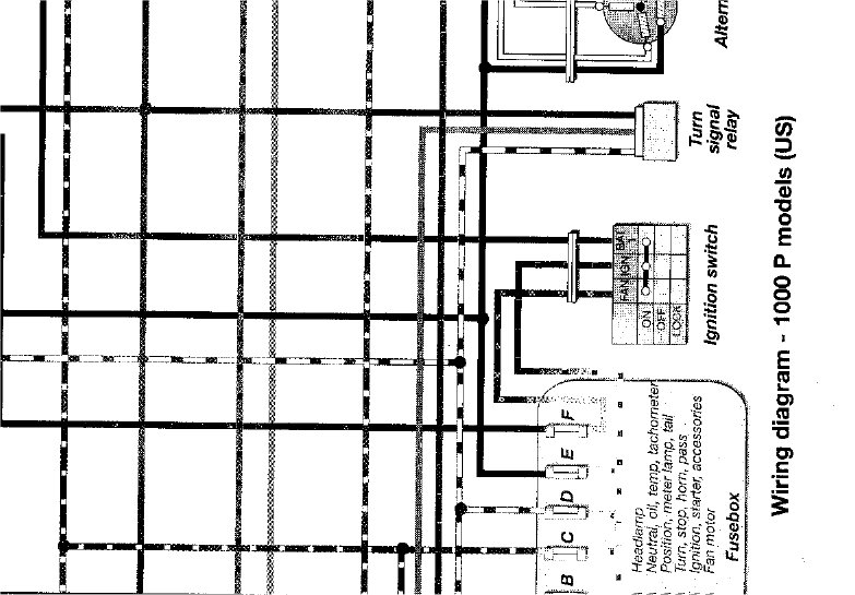
Should be three connections to your ignition switch. One wire comes from the battery. One goes to the fan motor via a fuse. One goes to your common at your fuse box. So, battery comes in "hot". Turn key on and all the fuses are now hot, which means all your electrics are hot. Also, a separate line goes to your fan motor with its own fuse (seperate because of amp draw from an electric fan motor) and the fan is turned on by the Thermostatic Fan Switch.
Your new ignition switch has 6 connections? Well, it could be made to work. There should be one connection that is marked "common" which would be your battery wire. Turn the switch on and see which two are now connected to the "common" connection. Put the line to the fuse box on one of those two and then put the fan motor wire to the other one. The other connections are not needed. Hope this helps.
P.S. You can test the new ignition switch connections in your hand with an ohm meter. That means NO POWER to the switch, just a switch in your hand. Put the red lead from your meter on the common connection point. Test the other connections by touching them with the black lead. NO connection should show conductivity. If they do, mark them as NO Good. Now turn on the switch and touch the ones that did not show conductivity. At least two should now show conductivity with the common. Use the common and those two connection for your wiring. Common = battery. Other two = fuse box and fan motor.
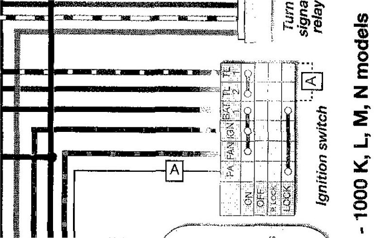
I see Steve posted the diagram while me fingers were typing what my little voice said to type. Use the Batt 1 for common. Use IGN for fuse box wire and use Fan for your fan motor wire. Should work. Just ignore TL1 TL2 and PA. The LOCK position will connect BAT, FAN, IGN and PA (must be an alarm?) or you could use it for a power source that you want available while the bike is in the locked position.
The big holes on the new part is what is going to anchor that puppy to the underside of your bulkhead. The old one has one big hole with a blind rivet looking thingy fastening the switch to the bulkhead and I assume the other big hole is under the wire housing (that we can't see) with another blind fastener. I would assume it has a blind rivet looking thingy also. Could be like a stove bolt where there is only one nut to worry about getting a wrench on while the blind end stays put, but I am not familiar with how to take that dude off. Those blind fastners might have a shaft with a clip groove at the other end. check on top for a c-clip.
Should be three connections to your ignition switch. One wire comes from the battery. One goes to the fan motor via a fuse. One goes to your common at your fuse box. So, battery comes in "hot". Turn key on and all the fuses are now hot, which means all your electrics are hot. Also, a separate line goes to your fan motor with its own fuse (seperate because of amp draw from an electric fan motor) and the fan is turned on by the Thermostatic Fan Switch.
Your new ignition switch has 6 connections? Well, it could be made to work. There should be one connection that is marked "common" which would be your battery wire. Turn the switch on and see which two are now connected to the "common" connection. Put the line to the fuse box on one of those two and then put the fan motor wire to the other one. The other connections are not needed. Hope this helps.
P.S. You can test the new ignition switch connections in your hand with an ohm meter. That means NO POWER to the switch, just a switch in your hand. Put the red lead from your meter on the common connection point. Test the other connections by touching them with the black lead. NO connection should show conductivity. If they do, mark them as NO Good. Now turn on the switch and touch the ones that did not show conductivity. At least two should now show conductivity with the common. Use the common and those two connection for your wiring. Common = battery. Other two = fuse box and fan motor.
I see Steve posted the diagram while me fingers were typing what my little voice said to type. Use the Batt 1 for common. Use IGN for fuse box wire and use Fan for your fan motor wire. Should work. Just ignore TL1 TL2 and PA. The LOCK position will connect BAT, FAN, IGN and PA (must be an alarm?) or you could use it for a power source that you want available while the bike is in the locked position.
Last edited by CBRriderNevada; May 1, 2009 at 10:09 PM.
Guest
Posts: n/a
Yes, I was writing all that stuff and then when I submitted it, yours was there and I did not want to delete it all. You are right, the best way is to get the right part. But with the new part you can now turn your switch into a electron s.ucking device laden monster! Now who does not want to create a monster?
 Make that puppy glow!!!
Now who does not want to create a monster? Make that puppy glow!!!
Thread Starter
|
Senior Member
Joined: Apr 2009
Posts: 104
Likes: 0
From: Antrim Northern Ireland
what holds the switch in is the round things at each side you can only see the one on the left hand side its the big rusty bit as for the 6 wire its the only one i could find will have to send it back and try to find a 3 wire

Redcoat, & Maxwell's Silver Hammer, MVN and curmudgeon
Joined: Dec 2007
Posts: 11,608
Likes: 5
From: Mud hut, Zululand
Best would be to buy the right switch.
You may be able to make that one work, but if not then you're stuck with it and will still have to buy another one..........
You may be able to make that one work, but if not then you're stuck with it and will still have to buy another one..........
Thread Starter
|
Senior Member
Joined: Apr 2009
Posts: 104
Likes: 0
From: Antrim Northern Ireland
i wish it was Torx bolt that holds it on but its that big round none bolt looking thing to the left hand side it has nothing on it to to get a grip if you look at the 2nd pic the holes at each side is what you use to fix it with