When you click on links to various merchants on this site and make a purchase, this can result in this site earning a commission. Affiliate programs and affiliations include, but are not limited to, the eBay Partner Network.
1991 Honda CBR1000f problems with Guage’s and charging system
Hello, my name is Chris new to this forum I am trying to figure out some things with my bike and have had not much success so that brings me here I’m hoping one of you guys can help thanks!
•the fuel sensor and the temp sensor peg out all the way up when the ignition is turned on
•the tachometer only works when the 10 amp fuse for the oil,neutral,side stand…etc is taken out of its place and as far as I know the MPH Guage isn’t working at all either so I’m at a loss here pretty much all my Guage’s aren’t working. The upper indicator lights work properly though and I’ve cleaned and checked all the pins and connectors if anyone has any advice it would be greatly appreciated
•the last problem I have is the charging system is not working properly I followed the other forum that said to hook up 12v pov and negative to the white and black wire off of the 6pin connector off of the alternator cover for the electro magnet and when I did that it worked fine charging up to 14.5v so now I’m trying to figure out why that black and white wire isn’t getting enough power in the first place, there is a 1v+ drop to the black and white wires when the ignition is turned on has anyone else solved this issue ?
thanks for all your help trying to get this thing going before summer
Most efficient troubleshooting (fastest and cheapest) is not to make any changes to system. Only passive measuring and testing only to let numbers tell you exactly what's wrong and how to fix it. Applying external power can often fry sensitive components.
Originally Posted by Cbro0827
•the fuel sensor and the temp sensor peg out all the way up when the ignition is turned on
Most common cause of this is broken wire between sensor and dash. Measure resistance to ground at sensor itself. Then measure again at sensor's wire at dash-connector to confirm.
Originally Posted by Cbro0827
•the tachometer only works when the 10 amp fuse for the oil,neutral,side stand…etc is taken out of its place and as far as I know the MPH Guage isn’t working at all either so I’m at a loss here pretty much all my Guage’s aren’t working. The upper indicator lights work properly though and I’ve cleaned and checked all the pins and connectors if anyone has any advice it would be greatly appreciated
Is this tach light not working? Or tach needle not showing engine-speed? If you pull that fuse, tach shows engine-speed properly?
Originally Posted by Cbro0827
•the last problem I have is the charging system is not working properly I followed the other forum that said to hook up 12v pov and negative to the white and black wire off of the 6pin connector off of the alternator cover for the electro magnet and when I did that it worked fine charging up to 14.5v so now I’m trying to figure out why that black and white wire isn’t getting enough power in the first place, there is a 1v+ drop to the black and white wires when the ignition is turned on has anyone else solved this issue ?
This is a broken wire. Measure and trace wiring to find broken wire.
- disconnect RR and alternator
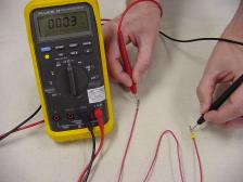
- measure resistance end-to-end of wht wire between RR and alternator connectors, ohms = ???
- measure resistance between RR mounting-bolt to chassis-ground, ohms = ???
- key ON, stop-switch=RUN, measure voltage at following points.
- blk wire @ RR connector, volts = ???
- blk wire @ alternator connector, volts = ???
At some point, you'll find power restored on blk wire. Broken section is in segment between where you found power vs. previous junction with no power. Might even be just corroded or disconnected plug. Now that you've found actual problem, you can fix it back to factory OEM configuration.
Also your voltage-drop between wire-ends is due to corrosion at connector terminals. Go through entire harness from beginning to end and unplug every connector. Apply some of this Deoxit compound to clean off corrosion, improve conductivity and seal against moisture to prevent future corrosion. Don't use dielectric (silicone) grease. It's not conductive, and doesn't do anything about existing corrosion.
Thank you Dmoh and Danno! I will check on both of those things today. And yeah Danno, the lights for the tach work good but when I have that fuse in, the tac doesn’t read any rpm but if I take it out it reads the rpm just fine ż
Hey you guys… A little more help would be appreciated greatly hopeful I’ll figure this blk wire out soon!
so it’s black and white wires going to an electro magnet so which one is the positive and which one is the negative I’ve traced the wires and cleaned connections to no avail, though I did hook up the white wire in the regular 6pin connector to where it is intended to go (the other half of the white wire to rectifier.) and I hooked the black wire to the headlight ground and it worked perfectly so I’m assuming the blk wire is a ground? Just want to make sure I think I am going to purchase a new engine start stop switch assembly
NO!!! Undo EVERYTHING YOU’ve done! You’re making things worse listening to those people!!!
Goal is 100% STOCK OEM WIRING ONLY!!! DO NOT ADD WIRING, DO NOT MAKE ANY EXTRA CONNECTIONS THAT WASN’T ALREADY THERE! Hopefully you haven’t fried RR artificially applying power where it doesn’t belong.
If you don’t have power where there should be power, find out WHY there’s no power there. It could be corroded/broken connector or wire just upstream. Solution is to fix that connector or broken spot on wire!. NOT artificially apply power by stringing another wire to that spot.
Parallel analogy is with your house lights and appliances. If you’ve lost functionality to your kitchen, bedroom, bathroom lights along with kitchen appliances, what are chances ALL those devices failed at exactly same time??? Would replacing all bulbs restore your appliances? Would you fix this by stringing new wires from pole directly to your kitchen, bedroom and bathroom lights?
What ONE device upstream from your lights and appliances could disable them all?
Perhaps looking at upstream causes of why power doesn’t make it to RR and stator might solve both problems at once without replacing single part and no stringing of new wires needed.
Last edited by dannoxyz; Mar 26, 2024 at 09:32 PM.
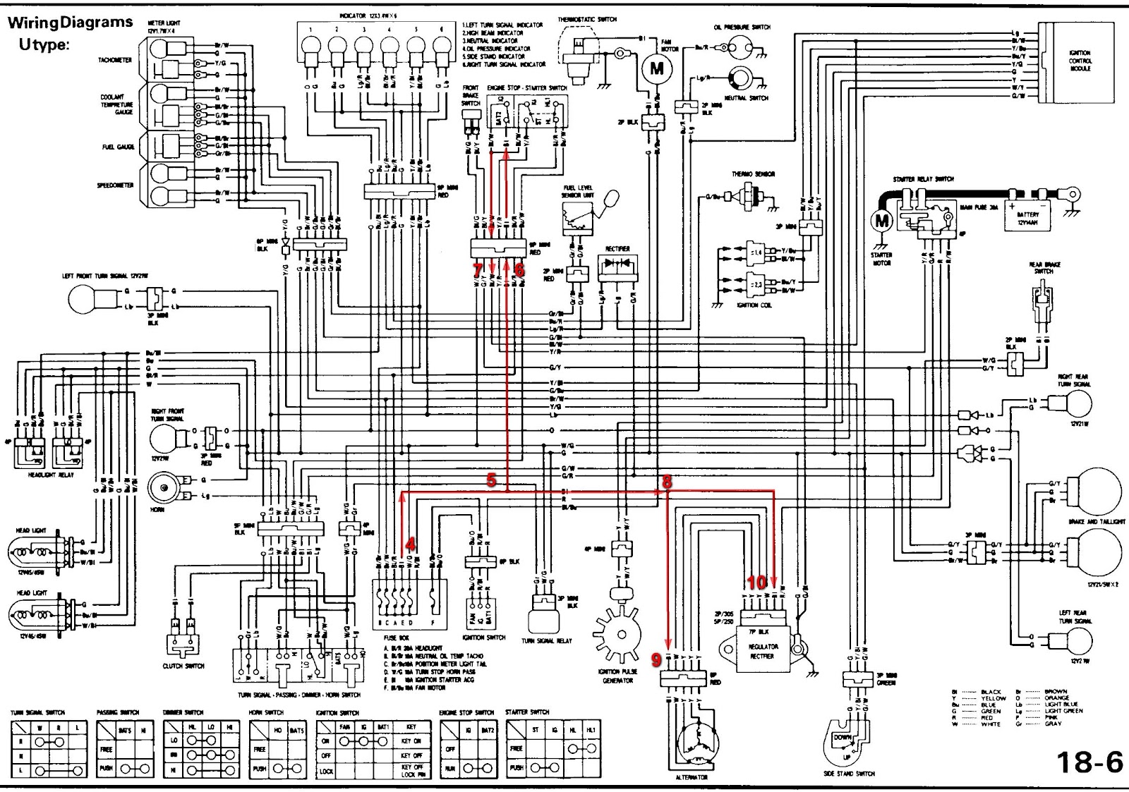
1. Trace each and every wire and make sure both end-points connect ONLY to where they belong on diagram.
2. Remove ALL extra wires and connections that don’t exist on diagram. Disconnect blk wire from headlight ground. Is this factory or extra wire you installed? Where is other end connected?
3. Then measure resistance of ALL wires end-to-end to make sure wire isn’t broken.
- stator wht wire only connects to regulator, so it shouldn’t touch anything else, hopefully you didn't fry regulator by applying power to this wire.
- stator blk wire also connects to regulator turn-ON terminal. This comes directly from fuse E. If you’ve got power on blk wire at fuse box end, and no power on same blk wire at other end by RR & stator, obviously you’ve got broken wire in between!!!
Unless you’re Superman and can see electrons moving inside wires, there’s absolutely zero way any human can just look at wires and determine its ability to conduct electricity. Luckiky, we have instruments that can.
4. Key ON, measure power at blk wire leaving fusebox, volts = ???
5. measure power on blk wire at junction splitting off to start/stop switch, volts = ???
6. measure power at blk wire at connector of right-controls, input start/stop switch, volts=??
7. Start/stop=RUN, measure power at blk/wht wire at connector of right-controls, output start/stop switch, volts=??
8. measure power on blk wire at junction going to stator & RR, volts = ???
9. measure power on blk wire at stator connector, volts = ???
10. measure power on blk wire at RR connector, volts = ???
These numbers in proper sequence will tell you exactly what problem is and how to fix it. It's between where you measured 0v and previous test-point that did have power. Most likely corroded or broken connector or wire along way.
If you measure full battery power for tests #6 and 7, then start/stop switch is perfectly fine. It doesn't have anything to do with power to RR and stator blk wire anyway, so stop wasting time on that. If you can crank bike, have power at igntion coils and ICM, start/stop switch is PERFECTLY FINE!!!. Doesn't have anything to do with power at blk wire @ stator and RR anyway. In fact, you can completely remove start/stop switch from bike completely and you'd STILL have power at blk wire @ stator and RR.
But… if you don’t have full battery power at blk wire at RR and stator, then you’ve got broken wire between fuse E and RR/stator. Replacing start/stop switch won’t fix anything because you’re replacing perfectly-working parts with brand-new perfectly working parts and nothing changes. And it doesn’t have anything to do with power on blk wire at RR or stator anyway!
Find actual problem before you make any changes to system. Otherwise you’re wasting time & money without any fixing anything. What measurements have you made where? And what are the numbers you measured?
btw - yel/grn wire drives tach directly from ICM. Measure resistance of that wire end-to-end. Then trace it from end-to-end to make sure nothing else touches it. Most likely there’s an extra wire someone strung to dash that’s interferring with normal power from 10a fuse.
Remember, don't get cause and effect mixed up. The result/effect you're seeing, no power, no tach, etc. is just by-product of real problem. Find what's causing problem, then fix that only (broken wire), and all effects of no power & no tach automatically fixes itself!
Last edited by dannoxyz; Mar 26, 2024 at 11:30 PM.
I’ve disconnected the wire I had from the headlight ground to the black wire as it isn’t factory I put it there to get it to charge.
the tac is getting signal but with the fuse in it will not let the tachometer work, if I take the fuse out the tac works fine… but that’s the least of my issues or might be connected to my other issues I don’t really know.
I tested the voltage of the black wire at all the different locations the regulator the connector upstream and the on off switch and the electromagnet itself also the fuse box and it is reading battery voltage across the board so I’m not entirely sure what is going on
I was under the impression that the black wire is supposed to be a ground but if it’s coming off of the fuse box then it can’t be I thought that the white wire was hot and black would be ground but i think I’m incorrect and just don’t really understand the system. I’m trying my best here to figure this out and I appreciate your help and patience
so just a recap the white and black wire are both showing battery voltage and I’m still not getting a charge.
that is when I put the red lead to the black or white wire with the black lead on the frame it’s reading battery voltage but still no charge :/
i am going to continue to test and see if any of the wires are touching each other when they shouldn’t be !
blk wire is battery power full-time. It turns ON regulator and provides power to stator
Wht wire should have zero voltage. It’s variable ground by regulator to adjust field-strength of stator coils
If you apply +13v —> to <— 13v , then no power flows because there’s no differential. Make sure that wht wire from stator ONLY goes to regulator. Get pin-outs of regulator and verify it’s at proper pin position on connector. Could very well have fried regulator by applying power to that wht wire.
10a fuse is only power to dash. If dash works with fuse pulled, someone rigged up some other power wire. Find it and remove completely if it doesn’t exist in diagram. Then put fuse back in.
Idea is to restore wiring back to 100% factory OEM condition and bike will work like brand-new off showroom floor.
Alright so upon further investigation my black and white wire were switched unfortunately and I just put this new electro sport rectifier on a few days ago…
so I switched them to there right areas and it still says 12+ v on both black and white so I assume I fried this brand new rectifier
I checked the white line and there is no visible short to the black wire
I am going to try the other two rectifiers I have then if that doesn’t work I’m going to grab the one off my friends bike if you got any feedback lmk as always I appreciate it!