
Carburetor Component Identification


Thread Starter
|
Super Moderator
Joined: Aug 2006
Posts: 5,304
Likes: 512
From: South Florida, USA
There are many questions about the carburetors, so I thought I'd post this in the Sticky section as a reference. I'll add additional images and information as time goes on.
We'll start with the Air Intake side. Carburetors are highly engineered devices that mix air and fuel. So naturally they need places to get air and they need places to get fuel. Air and fuel start to mix before they get into the intake or throat of the carburetor.
Now, for the Fuel side.
The same holds true for this side. Precicely machined passageways for fuel. The jets, and their openings connect the fuel in the bowl to passageways that allow the air from those air supplys to start mixing on there way to the throat of the carburetor. You'll notice that when you remove the jets, they extend down (or up) into the openings like a tube within a tube. This are is where the air and fuel first start to mix. Also notice that there are castings in the body of the carburetor, that are machined out that allow air and fuel to travel from one part of the carburetor to another. Since holes and only be drilled in straight lines, you'll also see brass plugs where after they drill, they plugged opening. This is usually at corners where they're trying to connect one passageway to another. I'll try to identify as many as I can here.
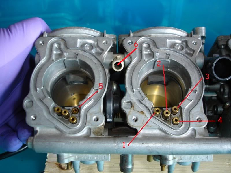
We'll start with the Air Intake side. Carburetors are highly engineered devices that mix air and fuel. So naturally they need places to get air and they need places to get fuel. Air and fuel start to mix before they get into the intake or throat of the carburetor.
- Air supply for choke circuit (ByStarter).
- Air supply for the main jet
- Slow Air Jet 2
- Slow Air Jet 1
- Plugged supply - passage used for Air-Cut circuit to help prevent backfire during decelleration
- Air supply for upper half of Float bowl. Comes from Outer vent or Inner vent depending on speed. Controlled by Air-Vent Solenoid, switches at 12 mph.
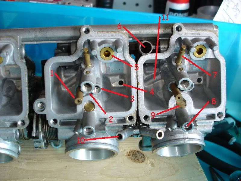
Now, for the Fuel side.
The same holds true for this side. Precicely machined passageways for fuel. The jets, and their openings connect the fuel in the bowl to passageways that allow the air from those air supplys to start mixing on there way to the throat of the carburetor. You'll notice that when you remove the jets, they extend down (or up) into the openings like a tube within a tube. This are is where the air and fuel first start to mix. Also notice that there are castings in the body of the carburetor, that are machined out that allow air and fuel to travel from one part of the carburetor to another. Since holes and only be drilled in straight lines, you'll also see brass plugs where after they drill, they plugged opening. This is usually at corners where they're trying to connect one passageway to another. I'll try to identify as many as I can here.
- Choke fuel supply (ByStarter)(not removable, but highly important for starting when cold.
- Main Jet/Needle Jet Holder (two pieces, one screwed the other).
- Slow Jet for idle and slow speed (low speed to half throttle).
- Air Supply for atmospheric pressure.
- Fuel supply seat for Float Valve.
- Fuel supply from fuel pump.
- Tube where Main Needle sits while in resting position.
- Pilot Screw (needs to be removed for proper cleaning, you should turn it in until it stops, counting the number of turns so you can put it back to where it came from if you're not going to be adjusting it).
- Plug for idle mixture supply passageway and machining bypass ports.
- Engine coolant to help prevent freezing of carburetors. Keeps throat warm.
- Hidden passageway for Choke fuel supply.
Last edited by IDoDirt; Jul 21, 2017 at 09:11 AM. Reason: Edited to fix photos.

Thread Starter
|
Super Moderator
Joined: Aug 2006
Posts: 5,304
Likes: 512
From: South Florida, USA
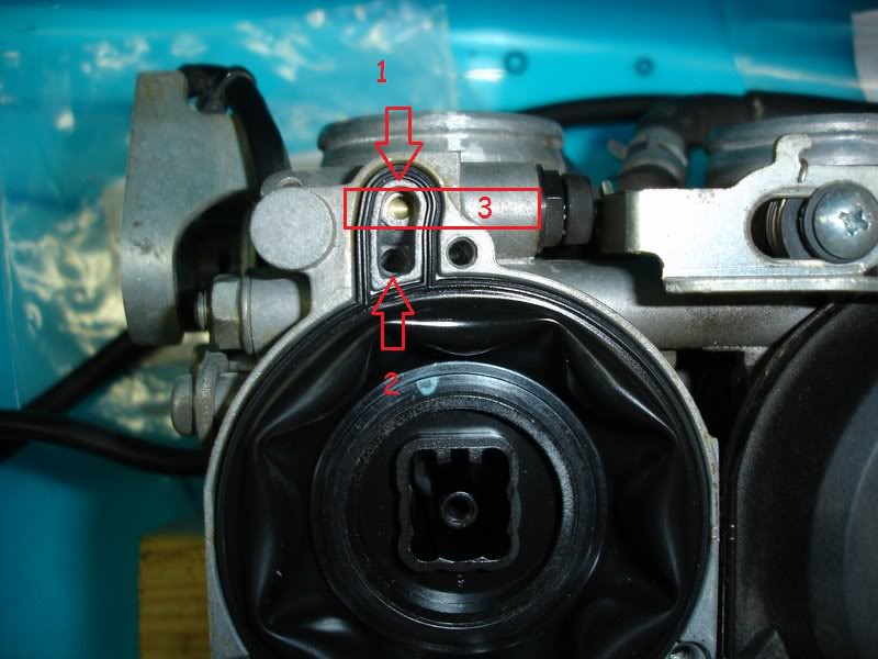
OK, here is how the Choke works. The idea of the choke, is to "richen" (is that a word) the Air-Fuel mixture for starting when the engine is cold. When you're trying to start the engine, the throttle is closed (the butterfly inside the throat of the carburetor and the only part that moves by twisting the throttle is closed). A pretty strong vacuum is created inside the the Intake passageway to draw fuel and air into the engine. A small amount of air is able to pass through the small openings in the front of the carburetor called Air Jets.
To add additional fuel and air, the choke lever opens a valve at the top of the carburetor near the vacuum slide.
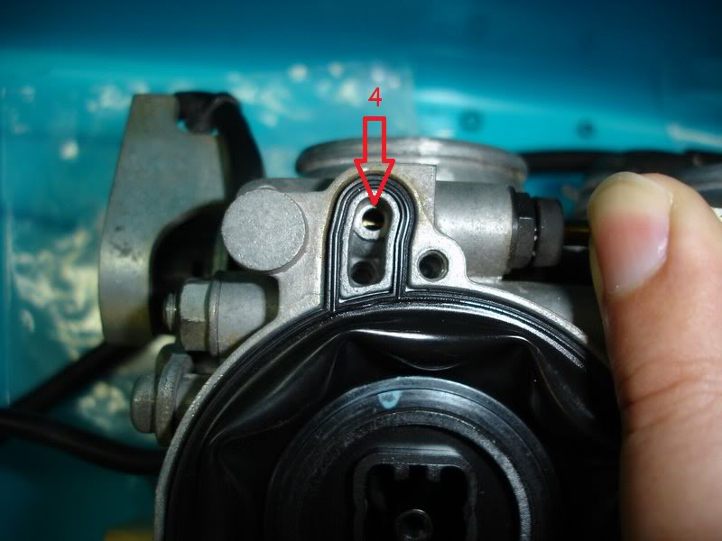
In this image you can see where the air and fuel go when the Choke valve is open.
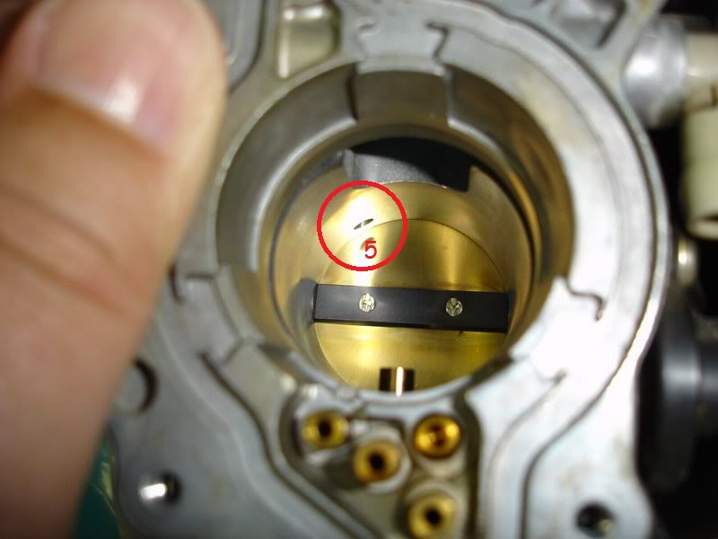
With the slide removed you can see the inlet side of the choke air passageway.
It's really critical that during the cleaning process you take the choke valve out (just a single plastic nut to the right of item #3) and make sure that all the passageways are clear. Remove any of the rubber parts before spraying with carburetor cleaner because it will damage them.
Something to keep in mind is that the choke can only function correctly if the throttle is closed. If you're twisting the throttle when starting, then there is no vacuum created to draw the fuel in through the choke passageways.
To add additional fuel and air, the choke lever opens a valve at the top of the carburetor near the vacuum slide.
- Small opening where fuel and air pass into the downstream side of the carburetor. The opening is currently blocked by the choke valve (it's closed)
- Air Inlet side where air enters from in front of the butterfly.
- Choke valve inside the body of the carburetor and actuated by the choke lever and cable.
In this image you can see where the air and fuel go when the Choke valve is open.
- 4, Choke valve open for air and fuel to pass through.
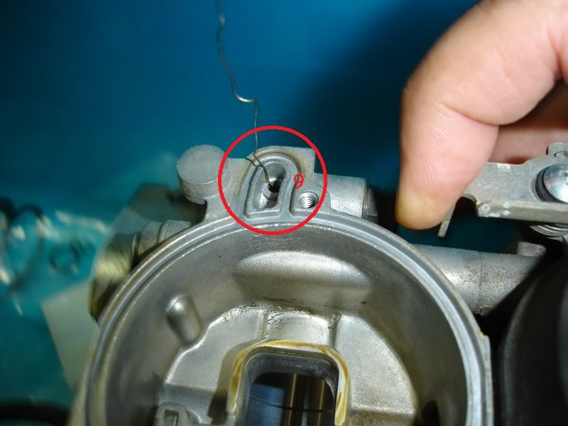
With the slide removed you can see the inlet side of the choke air passageway.
- Circle 5 Choke Air Inlet
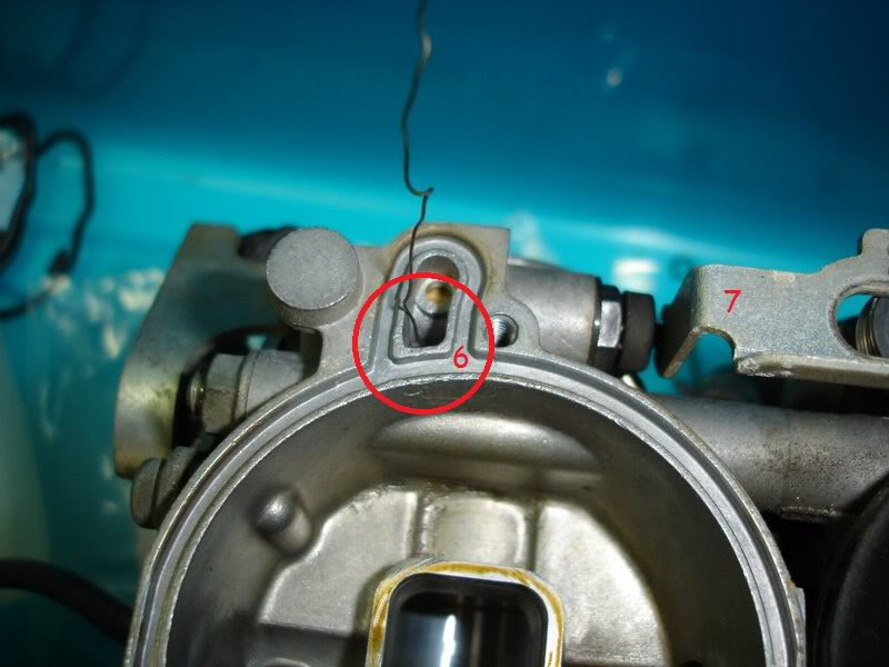
- In item 6 I've inserted a wire so you can see the inlet side on the top
- Item 7 is the Choke Actuator that opens all the choke valves at the same time.
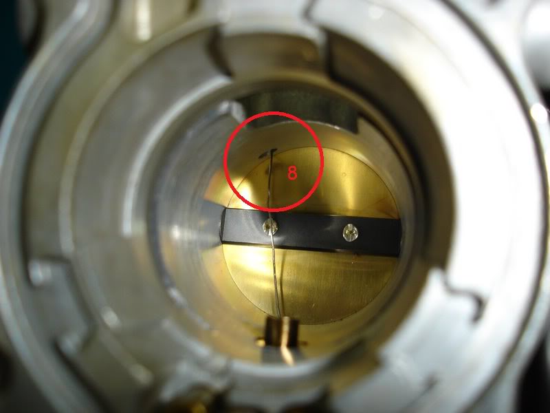
- Item 8 is the inlet side. You can't normally see this because the slide is in the way.
- Item 9 is where the air and fuel go down into the bore of the carburetor on the downstream side of the butterfly.
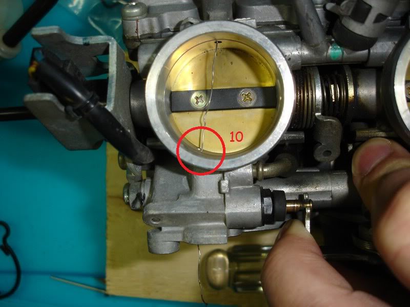
- Item 10 is where the air and fuel enter.
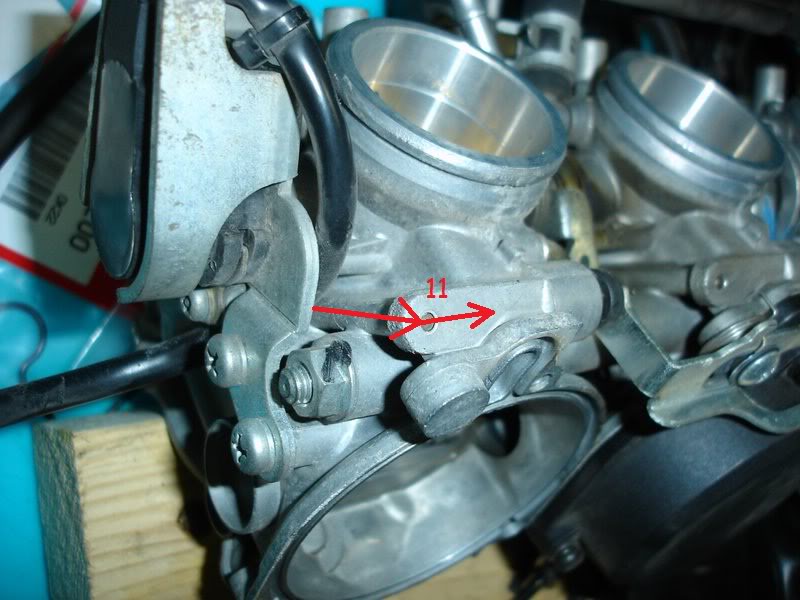
- Item 11 is the fuel passageway coming from the bottom of carburetor near the float. The line shows the path of the fuel. You can see the brass plugs where during manufacture they machine the passageways, then plug the openings.
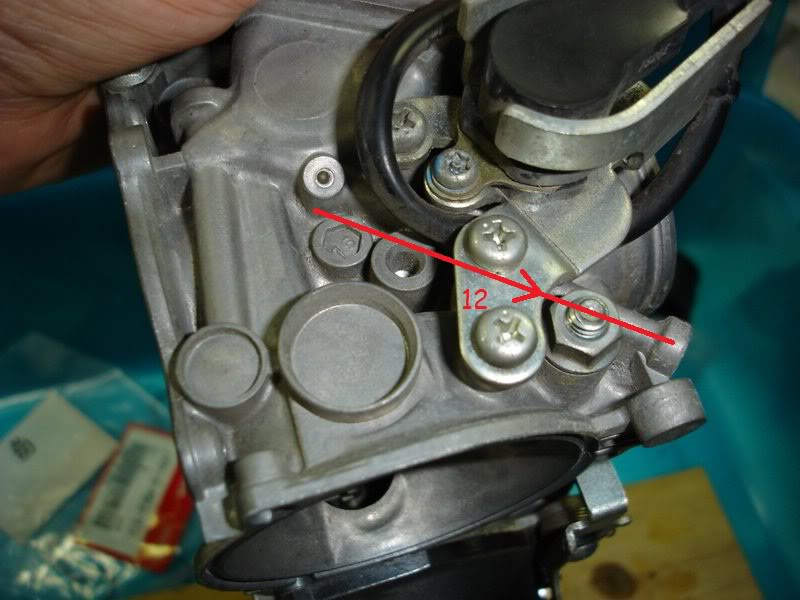
- Item 12 is the hidden passageway from the bowl up to the top of the carbutetor. Note the small brass plug near the left end of the line where they again machined a passageway to get to the bowl.
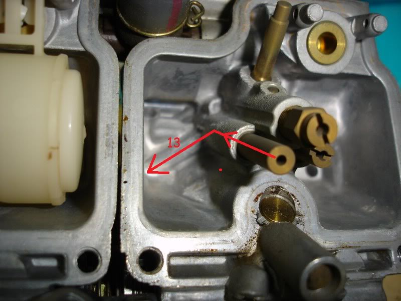
- Item 13 is where the fuel enters from the bowl through this small brass tube that you can't remove. If a bike sits for a long time with fuel in the carburetors,it is easily clogged. This passageway supplies the choke circuit.
It's really critical that during the cleaning process you take the choke valve out (just a single plastic nut to the right of item #3) and make sure that all the passageways are clear. Remove any of the rubber parts before spraying with carburetor cleaner because it will damage them.
Something to keep in mind is that the choke can only function correctly if the throttle is closed. If you're twisting the throttle when starting, then there is no vacuum created to draw the fuel in through the choke passageways.
Last edited by IDoDirt; Jul 25, 2017 at 06:53 AM. Reason: Edited to repair photo Links