Projection and Halo Install
#1
Okay so I am new here, and this is my first write up so give me some slack if its confusing but I am in the process of installing the projectors and doing the wiring so as i go along ill post updates and give you guys a wiring diagram.
So first taking the front fairing off and removing the headlight housing i didnt takes pics of but jondevos wrote a really nice write up of how to do it here so if you need it go here: https://cbrforum.com/forum/showthrea...light=jondevos.
Okay so once you get the headlight housing out of the fairing and you remove the halogen blubs, you then have the dreaded baking phase. I know a lot of people use heat guns, but I didnt have one so I put it in the oven at 225 F for around 12 min. Important things to note is that you want to line the oven rack with tin foil. You never want to put your housing directly on the rack. Also make sure the housing is not touching the sides as it can melt. I took it out and took a flat head screw driver and started working the lens and housing apart. Also, this may seem common sense, but the housing will be hot so be careful. I used a towel to hold onto it. After I got the light out, I first unlocked the clips surrounding and then wedged in the screw driver and started to carefully pry the housing apart. Take your time with this. There is no need to rush it and ruin your housing and then have to buy a new piece. If you find it to hard just put it back in the oven for another 3-4 min to soften the glue and then go back to prying it apart. Once you get it apart just grab onto it and carefully pull it apart.
Word of caution then when you do this, if you see any bent pieces of the housing just push them back in while its warm and the housing will then be fixed. Like I said its important to take your time and not to rush this. Be patient and it will come apart.
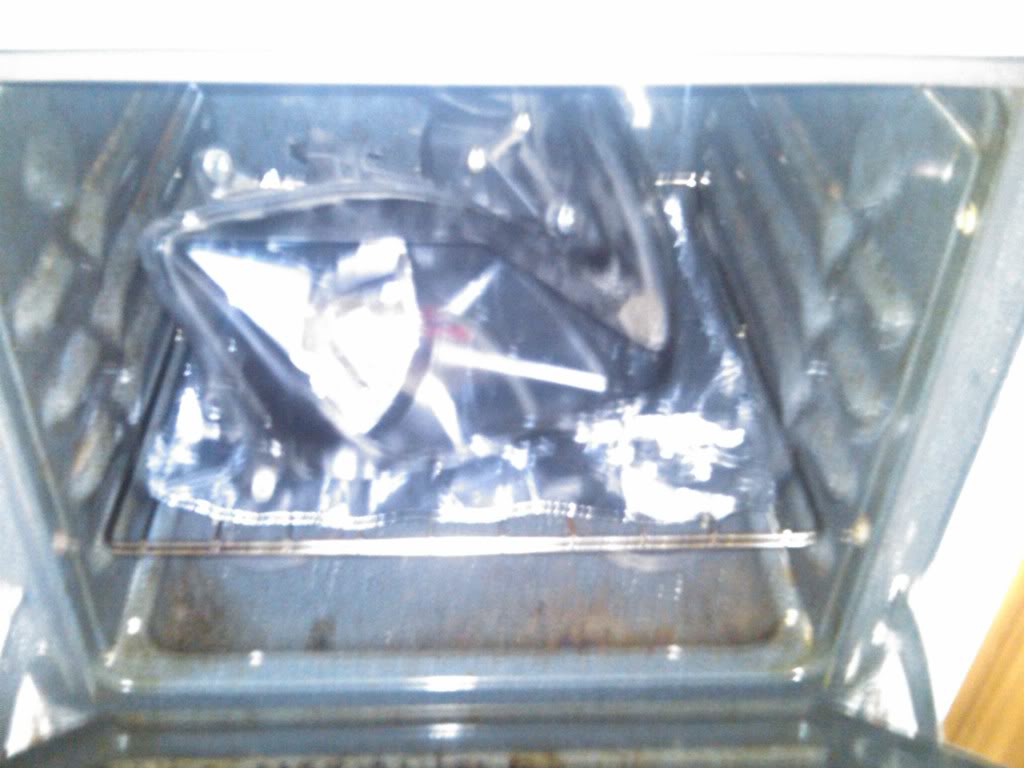
This is a picture of it in the oven. Notice the aluminum foil on the rack. Don't forget this or you will be really unhappy.
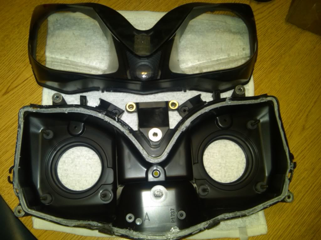
This is how it should look after you take apart the housing and remove the reflectors
Okay after that you can unscrew the 3 adjusting screws mounted into the reflector to remove the reflector. The reason i did this was because 1) apparently HID with reflectors are illegal and I didnt feel like dealing with any police and 2) i thought black would look so much sicker with the projectors in. The spray paint i used was Krylon Fusion Black. All it is a special paint that binds to plastic without primers. You want to do light coats and let it dry for 20 min in between coats. I know you may want to coat the whole reflector evenly with a lot of paint but if you do this it will drip and look really crappy. I did two coats of it and i think it looks good.
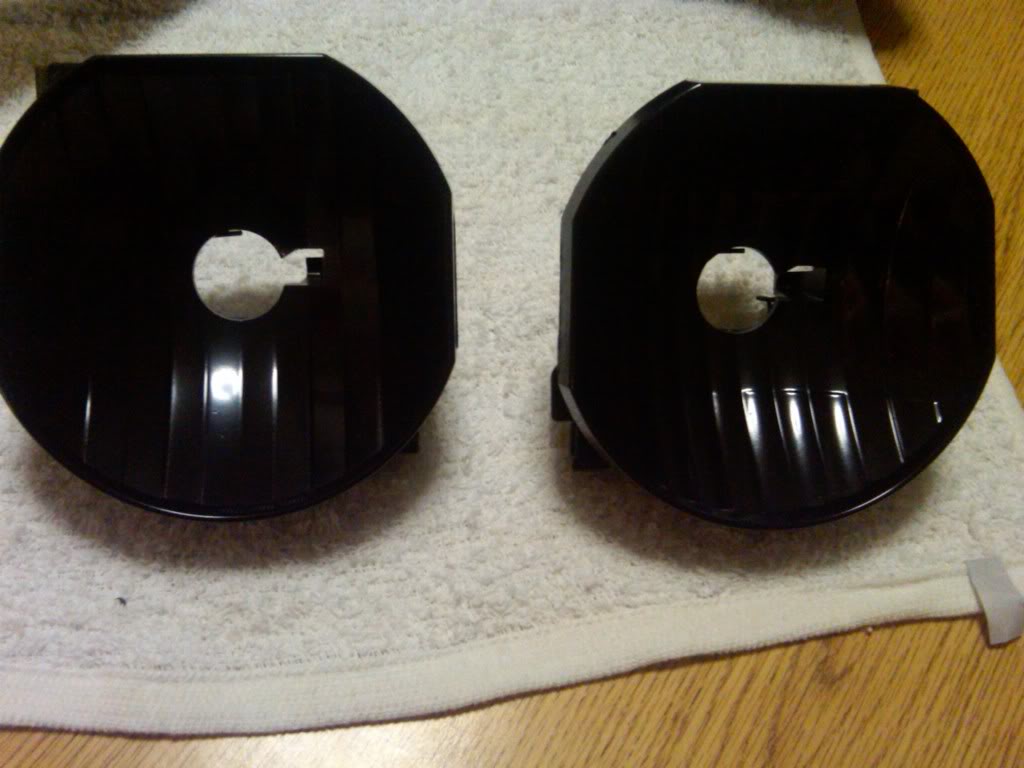
These are the painted reflectors
Okay now comes the fun part of putting the projectors in. The best way i found to do this was to remove the HID bulbs from the projector housing so it was easier to work with. Also remember to wear some sort of gloves, preferably latex or medical gloves. You dont want to get oil on the lights as it can cause hot spots and damage the bulb or light housing. In order to put the projectors in reinstall the housing and screw the adjusting screws as far as they can. Then place in the projector in and screw it in with first the alignment nut, then lock washer, and last the nut. Make sure these are right and secure as this is going to hold everything together. You want to check the front of the light housing to make sure everything is even.
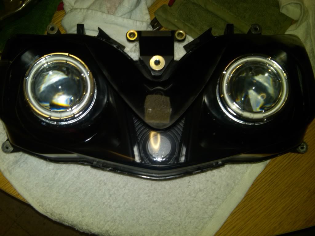
This is after projector were installed
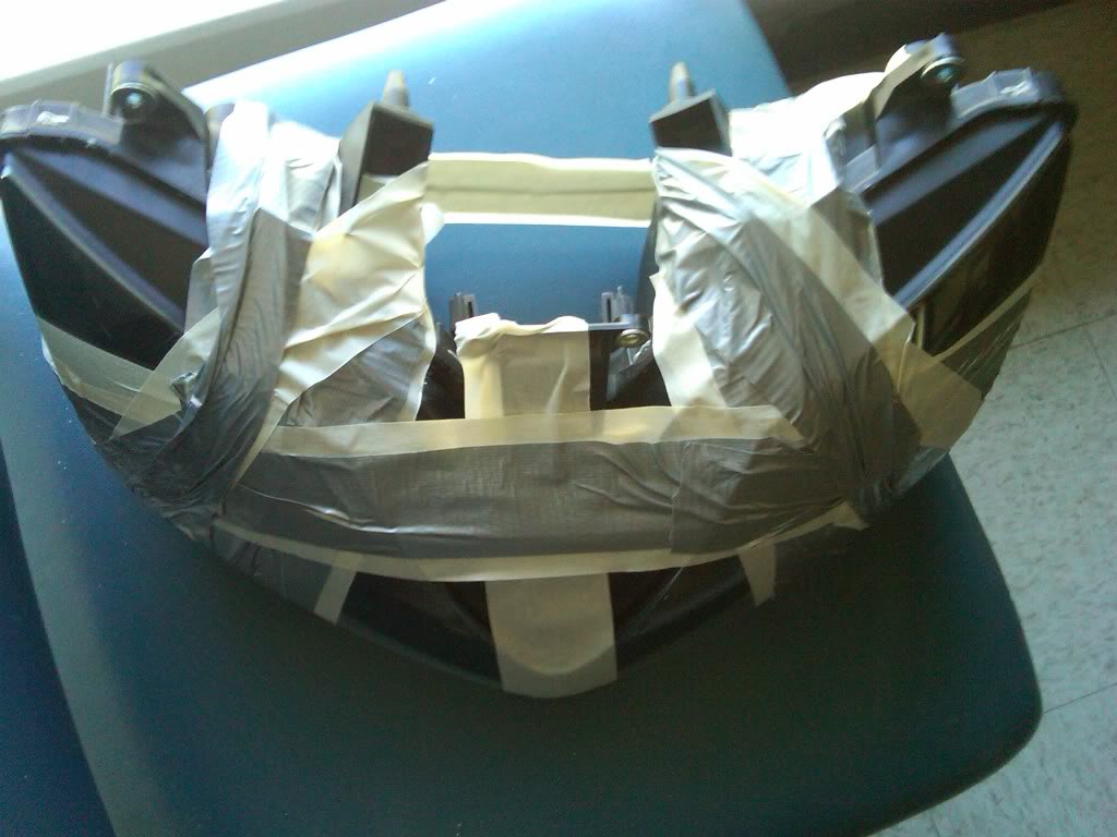
Okay once you have that, go back and reheat your oven back to 225 F. Make sure your bulbs are not in the housing as they can burst. Push the lens back onto the housing and push it together as close as you can. You probably wont be able to move it much so dont panic. Place the housing in the oven for 12 min or till the glue becomes soft. The CCFL (Halo) wiring will not melt at these temperatures. If you are nervous just check on it as its baking. After the glue is soft, take it out and push the lens and housing together. Try to get it as close as you can and make the clips snap back on. This will help hold it together. From this point after pushing it together I had to put it back in the oven for another 5 min to soften the glue further to compress lens and housing closer together. Again patience is key. Now me being slightly paranoid about this, I duct taped it to keep a lot of pressure on the housing. I applied masking tape first to the housing as I felt duck tape would be to strong and might damage it. I let it completely cool over night to make sure the glue hardened. I mean I am sure you could let this go for 3 hours and it would be fine, I may have just been paranoid. Either way the next morning, I unwrapped it, and the housing was together and everything looked fine. If you want you can apply an extra layer of silicon glue to the outside to ensure a seal but that is optional. I didnt.
This is the housing taped up
This is the housing the following morning (sorry bout the sun glare)
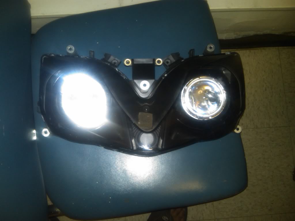
So I was happy with this and now put back on the rubber protectors ( no idea their real name) and pulled the wires through.
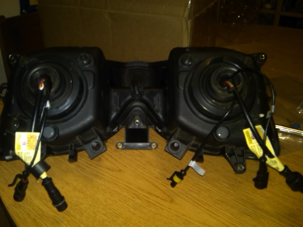
At this point the headlights were done and I was onto the wiring. I didnt put the headlight housing back in the front fairing fearing I may have to take it apart luckily this didnt happen. The next few pictures I am going to show you the wiring. I have written up a wiring diagram but Ill try to explain it as of now. Each HID wiring harness had two white wires for low beam, two blue wires for high beam, a red wire and black wire for CCFL, and then the standard connectors to the ballast and controller box. The black wire is ground obviously for the CCFL and the red is positive. The white and blue were the confusing ones. What I did not realize was the controller automatically determined which wire was which depending how you connect it, so you just need to make sure you choose two wires to be positive and two to be negative and do the same for the blue wires. Make sure you remember which is which. The other thing I did with mine was that I wanted a switch so I could run only the CCFL, only the lights, both, or have everything off. I did this so I could turn the lights off and not draw as much drain on my battery when I turned on the bike as the HID draw a lot of current on start up and it is bad for the battery. When I do the wiring diagram I will get a lot more detailed into the wiring and how connectors went were specifically but this is a rough detail for now.
So these are both harness attached with the wires just hand tied for now. I was setting up a trial run to make sure all the connections work. As you may be able to see, there are two sets of blue and white wires tied together, and the red and black are also tied together.
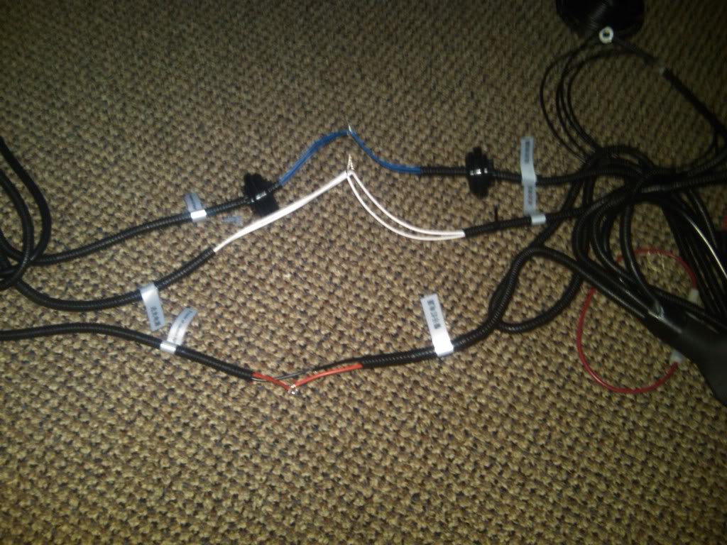
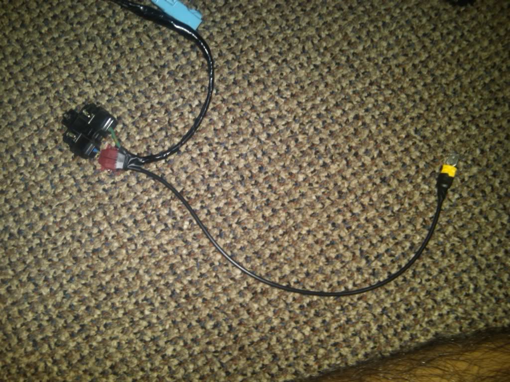
This is the splice into the low bean power wire. It has two splices one for the low beams and one for the CCFL. This allowed me to connect both of these to a switch.
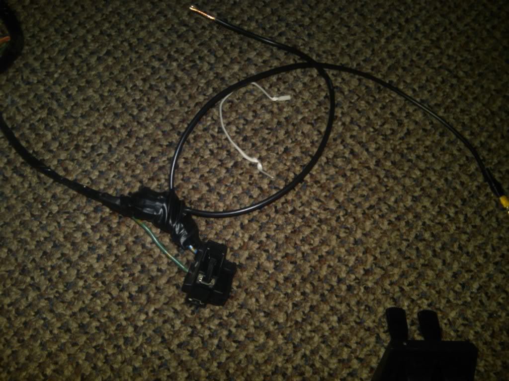
This is the splice in for the high beam. All this does is move a cover in the projector which allows for high beams to be shown.
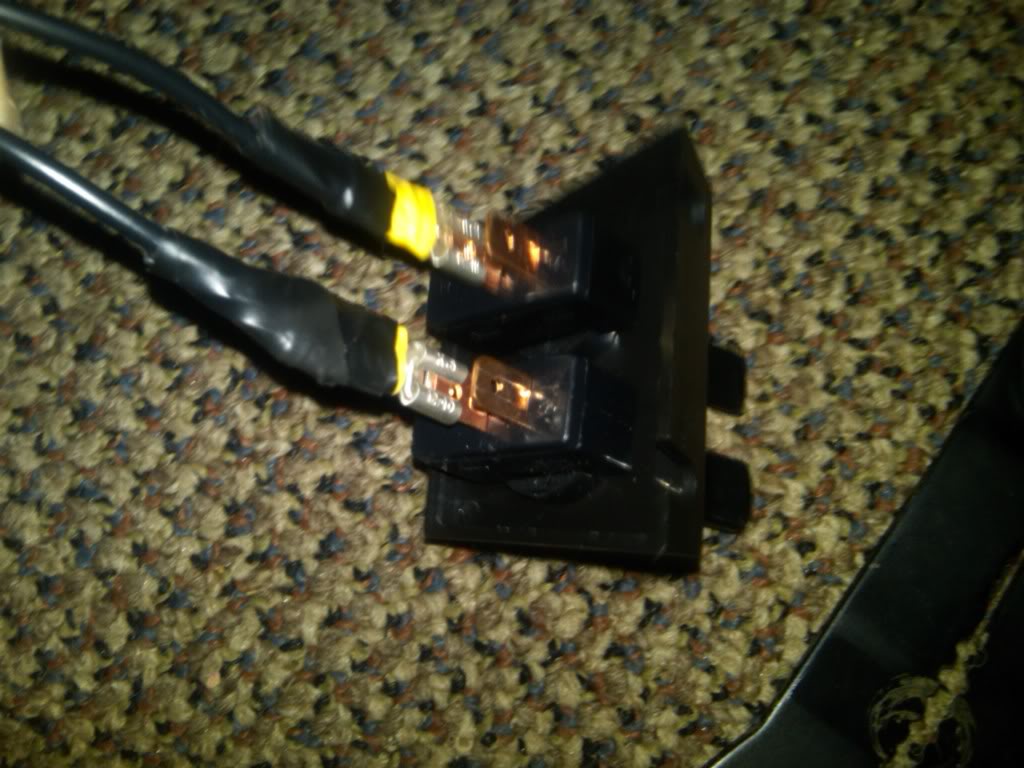
This is the switch. Its a simple two toggle switch for on and off where low beam and CCFL will be connected.
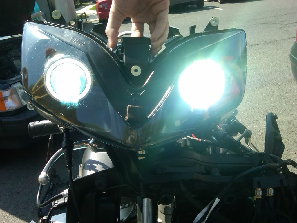
Okay I know that was abbreviated and I promise to go over that once I can actually write a wiring diagram and give you colors and tell you what goes where. But now I am on to the most exciting part. The cold run with wires just hand bound together and the lights just resting on top of the bike. I connected all the wires where they should go and tried it out. IT WORKED! Thank god. But here are the picks. I know its during the day so you cant see much, but it works and the high low toggle works like it should and so does the switch i installed.
These are just the halos on
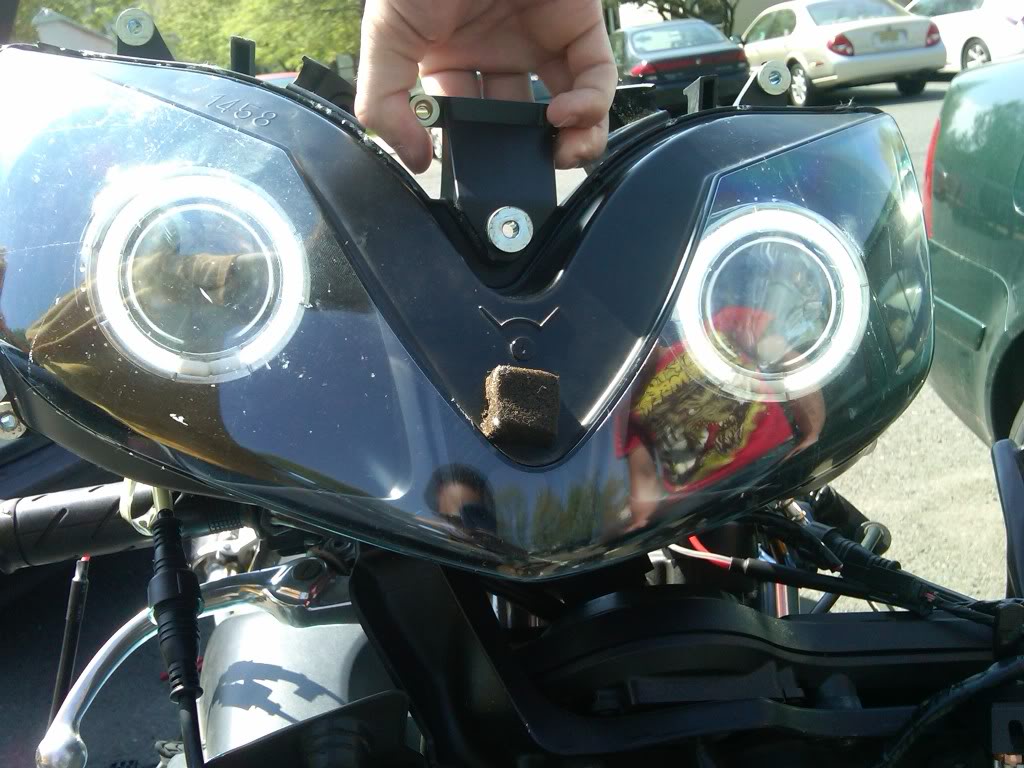
This is with halo and low beam
So after that work I came back and put the housing back in the front fairing and the result is:
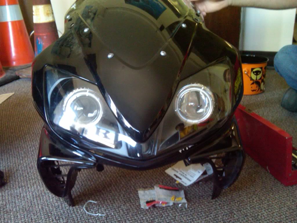
So that's where I am up too. It got dark and I didn't wanna wire it and try to install the ballast in the dark so I have to wait till tomorrow. But if you have questions Ill do my best to answer them and Ill try to get the wiring diagram up as soon as I can.
Update: Okay so I am updating this with the rest of the install and going to tell you all the problems I ran into but glad to say that it works now!
Okay so the last spot I left off i had finally put the housing back together and was ready for the install. So at this point it was time to prep all the wires get the ballast ready for the install.
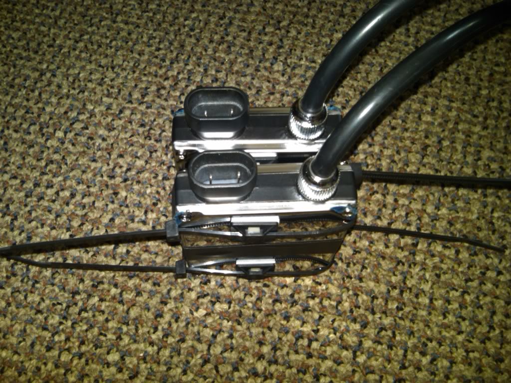
So this is the ballast. I zip tied them together and used a piece of electrical tape to hold them together. They don't get hot enough to do any damage to each other or other parts on the bike.
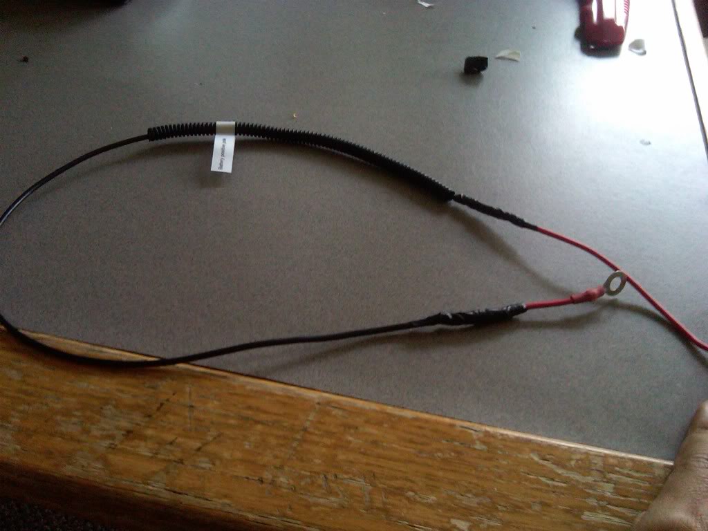
I also tied ring crimps on the ground wires to i put a screw through them. This was just because I knew it would make my life easier in the end and it was nothing more than that. Also I added wire to one of the power lines because it was too short.
Ground ring terminals
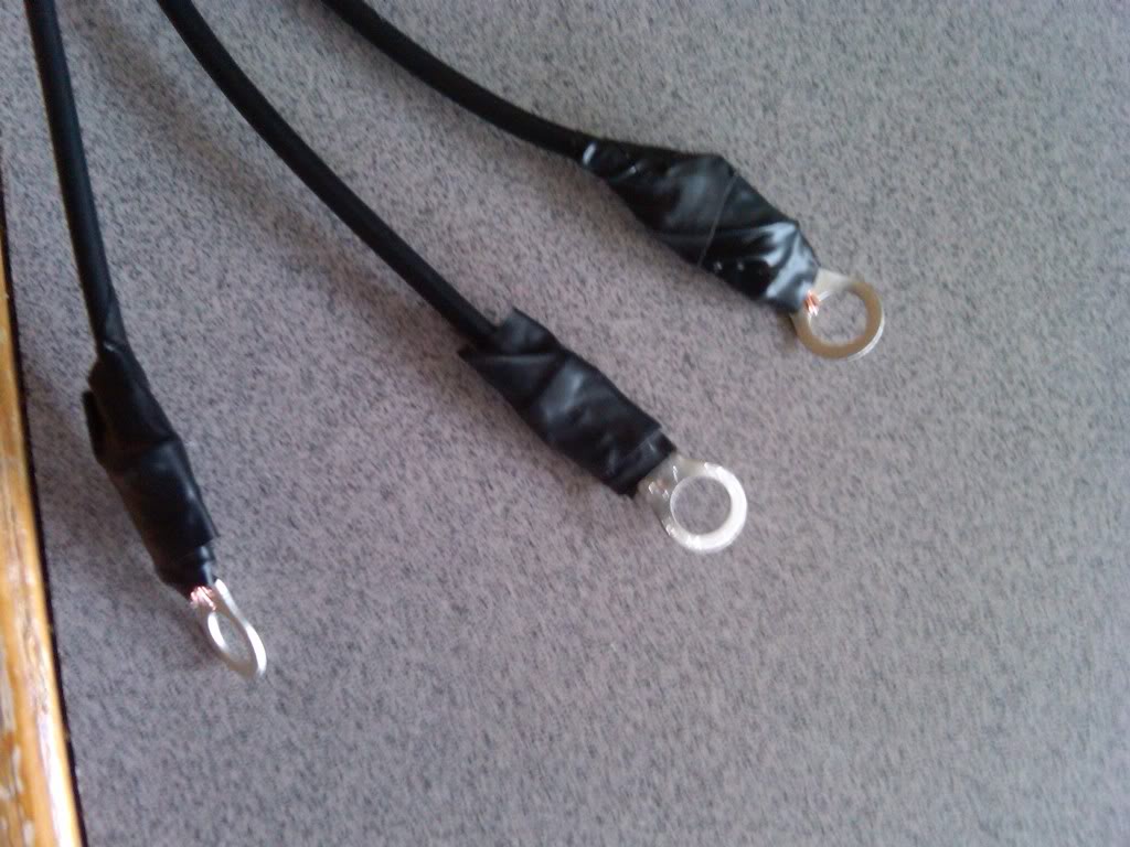
Lengthened Power Wire
Okay from here i put the main wire harness back on. I found if you take off the windscreen it was easier.
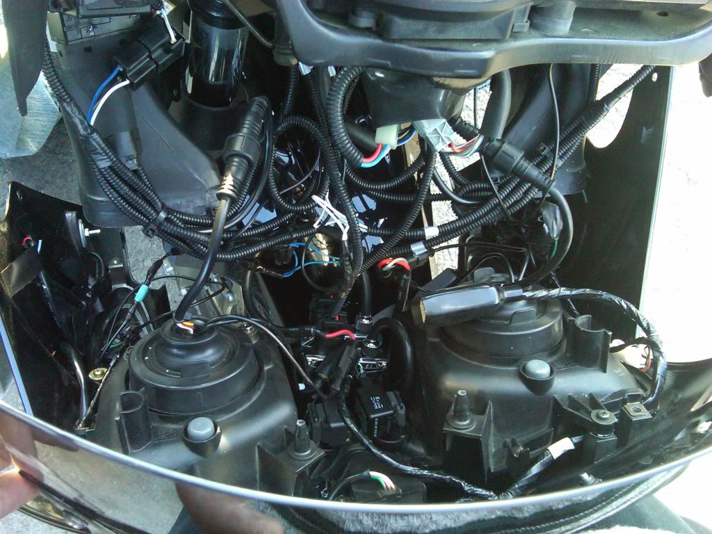
This is the wire harness on and everything is ready to go back on the bike. The spot under the headlight and turn relays is where I put the ballast in. You will this in a later picture
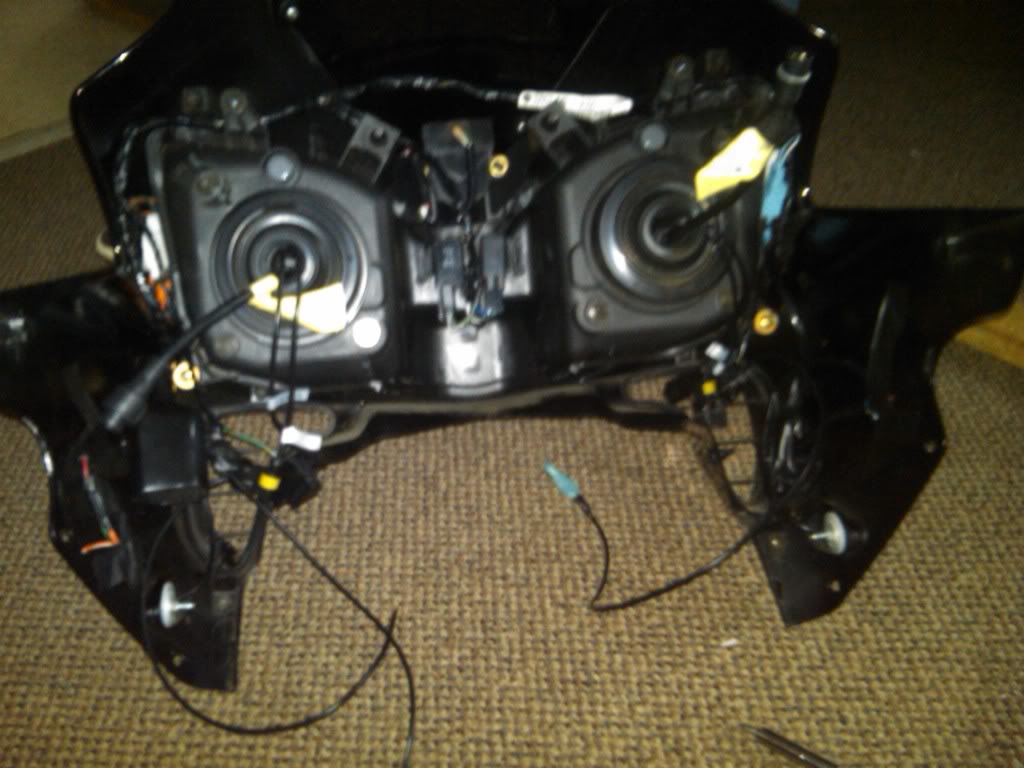
THIS IS WHAT YOU SHOULD NOT DO!
I originally installed the ballast on the frame of the bike in this convenient looking spot. The picture below is that spot.
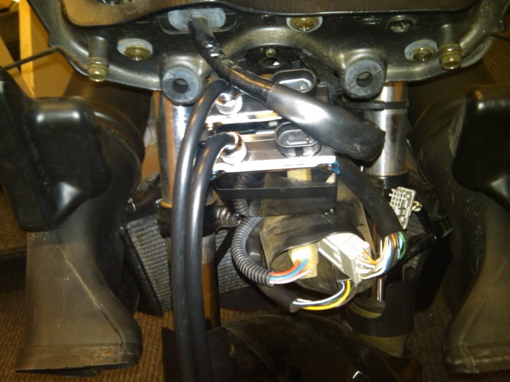
You would think spot works great but it doesn't. The front harness doesn't fit. When you do this and then mount your controllers on the forks you end up jamming your steering up and not being able to steer. Trust me this happens cause I did it and nearly dumped the bike into a parked car on a test drive. So word of caution do not do this even though it is really tempting.
Okay now back to the way you should do it. Like I said, I put the ballast under the relays in the front housing.
So after realizing the controllers don't fit on the forks, I needed a new place so off came those plastic resonators. They just pulled off so that was easy and I put a piece of duct tape over the holes and everything seemed okay. I zip tied the controllers in and fixed up the wiring a little bit. The result is this:
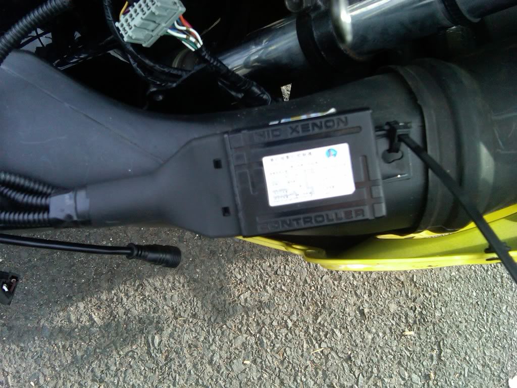
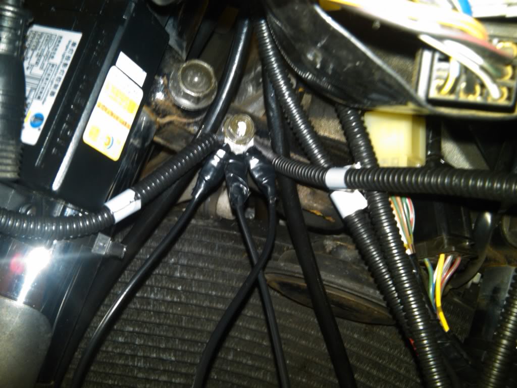
After making all the wire look pretty and make them follow the curve of the intake it was time to place the ground. I put in braid lines (which work great) so my old t-brake line connector was remove and left a screw on my fairing. So all 5 of my grounds went there. (Don't mind the controller on the fork as this was pre realizing my mistake)
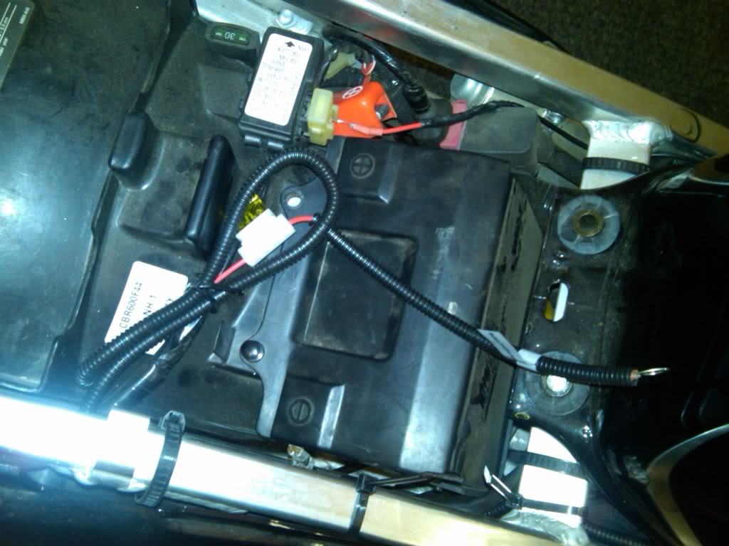
From here I then ran the two power cords under my fairings to the battery. I zip tied them along the way to make everything look nice.
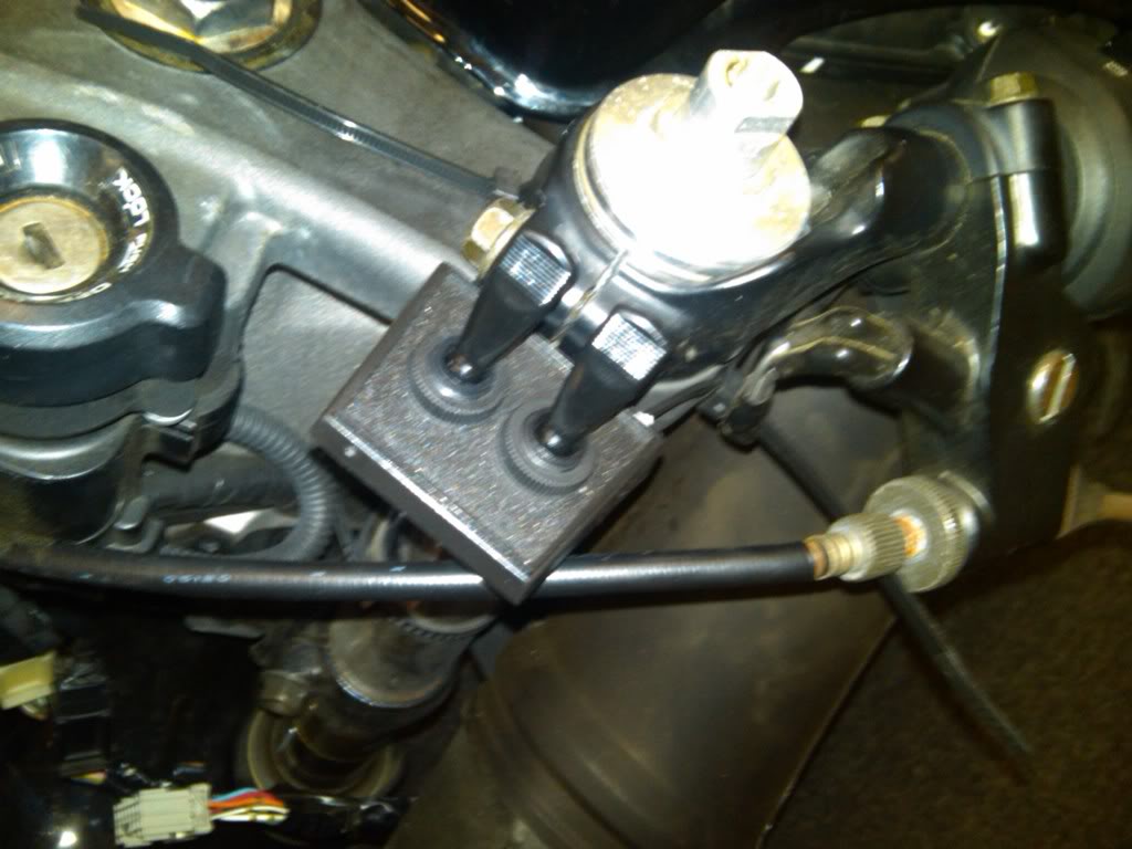
Okay last thing to do before wiring was to place the switch. I haven't decided to leave this switch here permanently or not yet but for now it does the job and everything works. Put the switch right off my clutch
Okay at this point now you have to put the front fairing back on and all your other fairings. First picture i side fairing and then front fairing. With the front wires try to keep them towards the center and out of the forks.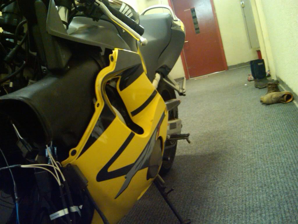
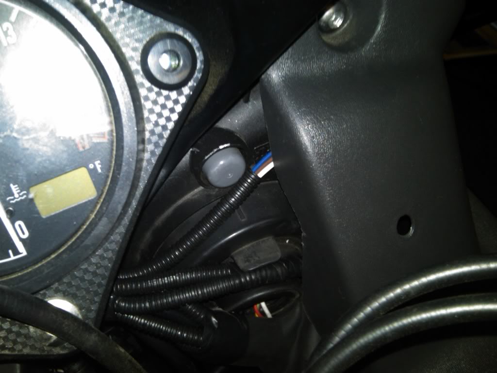
After that its just pushing everything back together and the wires near the handle bars should look something like this
Left Side:
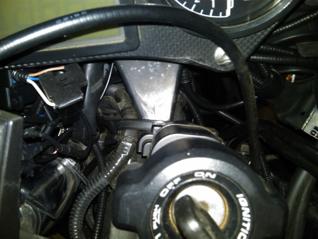
Right Side:
And hopefully once its all done it looks like this (lights are off here):
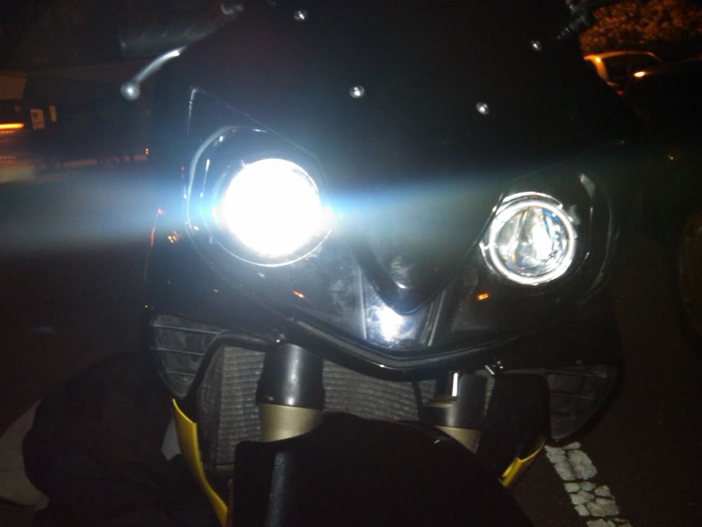
That is everything all done. I don't have any pictures yet of it lit cause it was mad dark when i finished and the camera was just not having it so those still need to be done also i am working on making a logical wiring diagram and once i do i will post it up. Hope this helps and any questions ask.
Also taking off the resonators has done nothing to harm the performance of the bike. To be honest, I have actually found shifting smoother than before. I doubt really see how this connects and I don't think it does just an observation
So first taking the front fairing off and removing the headlight housing i didnt takes pics of but jondevos wrote a really nice write up of how to do it here so if you need it go here: https://cbrforum.com/forum/showthrea...light=jondevos.
Okay so once you get the headlight housing out of the fairing and you remove the halogen blubs, you then have the dreaded baking phase. I know a lot of people use heat guns, but I didnt have one so I put it in the oven at 225 F for around 12 min. Important things to note is that you want to line the oven rack with tin foil. You never want to put your housing directly on the rack. Also make sure the housing is not touching the sides as it can melt. I took it out and took a flat head screw driver and started working the lens and housing apart. Also, this may seem common sense, but the housing will be hot so be careful. I used a towel to hold onto it. After I got the light out, I first unlocked the clips surrounding and then wedged in the screw driver and started to carefully pry the housing apart. Take your time with this. There is no need to rush it and ruin your housing and then have to buy a new piece. If you find it to hard just put it back in the oven for another 3-4 min to soften the glue and then go back to prying it apart. Once you get it apart just grab onto it and carefully pull it apart.
Word of caution then when you do this, if you see any bent pieces of the housing just push them back in while its warm and the housing will then be fixed. Like I said its important to take your time and not to rush this. Be patient and it will come apart.
This is a picture of it in the oven. Notice the aluminum foil on the rack. Don't forget this or you will be really unhappy.

This is how it should look after you take apart the housing and remove the reflectors

Okay after that you can unscrew the 3 adjusting screws mounted into the reflector to remove the reflector. The reason i did this was because 1) apparently HID with reflectors are illegal and I didnt feel like dealing with any police and 2) i thought black would look so much sicker with the projectors in. The spray paint i used was Krylon Fusion Black. All it is a special paint that binds to plastic without primers. You want to do light coats and let it dry for 20 min in between coats. I know you may want to coat the whole reflector evenly with a lot of paint but if you do this it will drip and look really crappy. I did two coats of it and i think it looks good.
These are the painted reflectors

Okay now comes the fun part of putting the projectors in. The best way i found to do this was to remove the HID bulbs from the projector housing so it was easier to work with. Also remember to wear some sort of gloves, preferably latex or medical gloves. You dont want to get oil on the lights as it can cause hot spots and damage the bulb or light housing. In order to put the projectors in reinstall the housing and screw the adjusting screws as far as they can. Then place in the projector in and screw it in with first the alignment nut, then lock washer, and last the nut. Make sure these are right and secure as this is going to hold everything together. You want to check the front of the light housing to make sure everything is even.
This is after projector were installed

Okay once you have that, go back and reheat your oven back to 225 F. Make sure your bulbs are not in the housing as they can burst. Push the lens back onto the housing and push it together as close as you can. You probably wont be able to move it much so dont panic. Place the housing in the oven for 12 min or till the glue becomes soft. The CCFL (Halo) wiring will not melt at these temperatures. If you are nervous just check on it as its baking. After the glue is soft, take it out and push the lens and housing together. Try to get it as close as you can and make the clips snap back on. This will help hold it together. From this point after pushing it together I had to put it back in the oven for another 5 min to soften the glue further to compress lens and housing closer together. Again patience is key. Now me being slightly paranoid about this, I duct taped it to keep a lot of pressure on the housing. I applied masking tape first to the housing as I felt duck tape would be to strong and might damage it. I let it completely cool over night to make sure the glue hardened. I mean I am sure you could let this go for 3 hours and it would be fine, I may have just been paranoid. Either way the next morning, I unwrapped it, and the housing was together and everything looked fine. If you want you can apply an extra layer of silicon glue to the outside to ensure a seal but that is optional. I didnt.
This is the housing taped up

This is the housing the following morning (sorry bout the sun glare)

So I was happy with this and now put back on the rubber protectors ( no idea their real name) and pulled the wires through.

At this point the headlights were done and I was onto the wiring. I didnt put the headlight housing back in the front fairing fearing I may have to take it apart luckily this didnt happen. The next few pictures I am going to show you the wiring. I have written up a wiring diagram but Ill try to explain it as of now. Each HID wiring harness had two white wires for low beam, two blue wires for high beam, a red wire and black wire for CCFL, and then the standard connectors to the ballast and controller box. The black wire is ground obviously for the CCFL and the red is positive. The white and blue were the confusing ones. What I did not realize was the controller automatically determined which wire was which depending how you connect it, so you just need to make sure you choose two wires to be positive and two to be negative and do the same for the blue wires. Make sure you remember which is which. The other thing I did with mine was that I wanted a switch so I could run only the CCFL, only the lights, both, or have everything off. I did this so I could turn the lights off and not draw as much drain on my battery when I turned on the bike as the HID draw a lot of current on start up and it is bad for the battery. When I do the wiring diagram I will get a lot more detailed into the wiring and how connectors went were specifically but this is a rough detail for now.
So these are both harness attached with the wires just hand tied for now. I was setting up a trial run to make sure all the connections work. As you may be able to see, there are two sets of blue and white wires tied together, and the red and black are also tied together.

This is the splice into the low bean power wire. It has two splices one for the low beams and one for the CCFL. This allowed me to connect both of these to a switch.

This is the splice in for the high beam. All this does is move a cover in the projector which allows for high beams to be shown.

This is the switch. Its a simple two toggle switch for on and off where low beam and CCFL will be connected.

Okay I know that was abbreviated and I promise to go over that once I can actually write a wiring diagram and give you colors and tell you what goes where. But now I am on to the most exciting part. The cold run with wires just hand bound together and the lights just resting on top of the bike. I connected all the wires where they should go and tried it out. IT WORKED! Thank god. But here are the picks. I know its during the day so you cant see much, but it works and the high low toggle works like it should and so does the switch i installed.
These are just the halos on

This is with halo and low beam

So after that work I came back and put the housing back in the front fairing and the result is:

So that's where I am up too. It got dark and I didn't wanna wire it and try to install the ballast in the dark so I have to wait till tomorrow. But if you have questions Ill do my best to answer them and Ill try to get the wiring diagram up as soon as I can.
Update: Okay so I am updating this with the rest of the install and going to tell you all the problems I ran into but glad to say that it works now!
Okay so the last spot I left off i had finally put the housing back together and was ready for the install. So at this point it was time to prep all the wires get the ballast ready for the install.
So this is the ballast. I zip tied them together and used a piece of electrical tape to hold them together. They don't get hot enough to do any damage to each other or other parts on the bike.

I also tied ring crimps on the ground wires to i put a screw through them. This was just because I knew it would make my life easier in the end and it was nothing more than that. Also I added wire to one of the power lines because it was too short.
Ground ring terminals

Lengthened Power Wire

Okay from here i put the main wire harness back on. I found if you take off the windscreen it was easier.
This is the wire harness on and everything is ready to go back on the bike. The spot under the headlight and turn relays is where I put the ballast in. You will this in a later picture

THIS IS WHAT YOU SHOULD NOT DO!
I originally installed the ballast on the frame of the bike in this convenient looking spot. The picture below is that spot.

You would think spot works great but it doesn't. The front harness doesn't fit. When you do this and then mount your controllers on the forks you end up jamming your steering up and not being able to steer. Trust me this happens cause I did it and nearly dumped the bike into a parked car on a test drive. So word of caution do not do this even though it is really tempting.
Okay now back to the way you should do it. Like I said, I put the ballast under the relays in the front housing.
So after realizing the controllers don't fit on the forks, I needed a new place so off came those plastic resonators. They just pulled off so that was easy and I put a piece of duct tape over the holes and everything seemed okay. I zip tied the controllers in and fixed up the wiring a little bit. The result is this:

After making all the wire look pretty and make them follow the curve of the intake it was time to place the ground. I put in braid lines (which work great) so my old t-brake line connector was remove and left a screw on my fairing. So all 5 of my grounds went there. (Don't mind the controller on the fork as this was pre realizing my mistake)

From here I then ran the two power cords under my fairings to the battery. I zip tied them along the way to make everything look nice.

Okay last thing to do before wiring was to place the switch. I haven't decided to leave this switch here permanently or not yet but for now it does the job and everything works. Put the switch right off my clutch

Okay at this point now you have to put the front fairing back on and all your other fairings. First picture i side fairing and then front fairing. With the front wires try to keep them towards the center and out of the forks.


After that its just pushing everything back together and the wires near the handle bars should look something like this
Left Side:

Right Side:

And hopefully once its all done it looks like this (lights are off here):

That is everything all done. I don't have any pictures yet of it lit cause it was mad dark when i finished and the camera was just not having it so those still need to be done also i am working on making a logical wiring diagram and once i do i will post it up. Hope this helps and any questions ask.
Also taking off the resonators has done nothing to harm the performance of the bike. To be honest, I have actually found shifting smoother than before. I doubt really see how this connects and I don't think it does just an observation
Last edited by waddleboy; 04-22-2010 at 06:47 PM.
#8
I havent really gotten into the controller units. I have been stuck trying to figure out where the controllers go. I think i am going to mount them on the front of my forks. I wont know till tomorrow or sunday how they look but once i put them in i will write an update where i put them
#9
n stuc
I havent really gotten into the controller units. I have been stuck trying to figure out where the controllers go. I think i am going to mount them on the front of my forks. I wont know till tomorrow or sunday how they look but once i put them in i will write an update where i put them
I havent really gotten into the controller units. I have been stuck trying to figure out where the controllers go. I think i am going to mount them on the front of my forks. I wont know till tomorrow or sunday how they look but once i put them in i will write an update where i put them
#10
I would say that on front of forks is probably a bad spot as they will get wet there. I doubt they are waterproof let alone even much water resisitant. I havnt completely put mine back together but today I took the intake resinators off (the part that sticks out on top of the intake tubes that hooks to fairing stay) and have set them there. Looks like I am going to mount them there and they will hide nicely under the intake covers. Tomorrow I will take more pictures once I decide and will post up what I did. I redid all my wiring today and all is working well. Added in a second switch so that I can turn off the HID when starting the bike or if I feel like running with just the angel eyes on. I velcroed my ballasts and the relays for hi/low beams in between the headlights. I took pictures along the way so will post up hopefully tomorrow.
Only question I have is did you remove the resonator completely off the bike and keeping it off? How did you mount the controllers and keep the resonator cover on? Id like to see pics and Ill show you mine once i finish and give the pics of my turning disaster and hopefully it fixed!


