
HOW TO: LED Passenger Peg Break/Turn Signals (step by set w/ pics)


Thread Starter
|
Junior Member
Joined: Feb 2011
Posts: 7
Likes: 1
From: Minneapolis, MN
Hello All,
This is my first post; however, I've lurked for quite some time. This winter I decided to begin a few projects on my 02 CBR 600 F4i. I ordered a Hotbodies undertail kit and Yoshimura TRS s/s slip on. After doing some research I came to the conclusion that the stock LED break/turn signals in the Hotbodies undertail were not going to satisfy my safety standards. For those that don't know the Hotbodies undertail stock tail light does decrease visibility from rear in comparison to the stock tail light. My way to remedy the situation was to add passenger peg LED tail lights and turn signals. It turned out great.
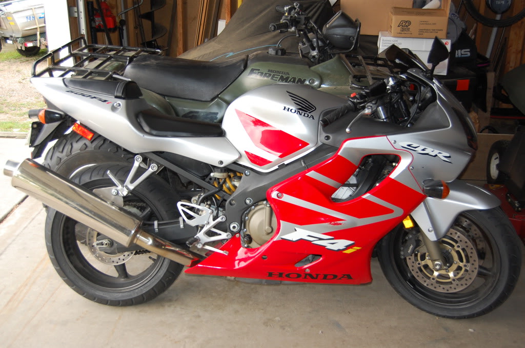
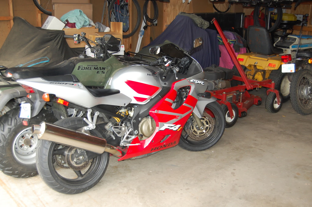
Here is what my bike looked like before I started any mods.
This guide will focus mostly on the LED Tail lights. However, I'll add in notes on the undertail installation and the exhaust installation. With pics of course! Any questions feel free to PM or reply. Also please note that I'm a complete novice when it comes to wiring. There are probably better ways but this is how I chose to do it.
STEP 1: Pegs
Decide what type of LED set up you want. You can basically do whatever you want with as many lights as you want. I decided to add 5 lights to each side. The top 3 are wired as break lights and are red. The bottom 2 are amber turn signals and are wired as such.
Decide on the type of LED you wish to use. I ordered 5mm 8,000 MCD LEDS with a 30 degree viewing angle. They are visually directional so keep that in mind.
Remove the passenger pegs. Make sure to mark which one is right and left. Believe me, you do not want to be drilling holes on the wrong side of the peg. Which can easily happen when you get a workbench full of tools/parts.
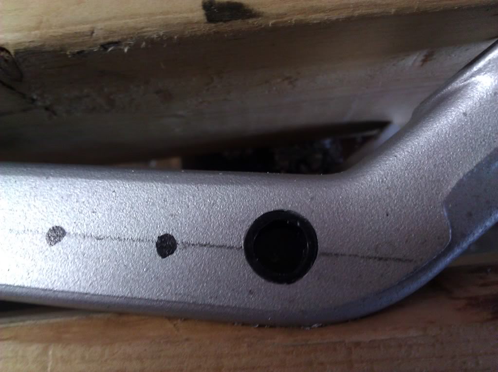
As for measuring. I suck. I can admit that. I measured out and found the centerline of the peg. I then measured 1.5 cm intervals for hole drilling.
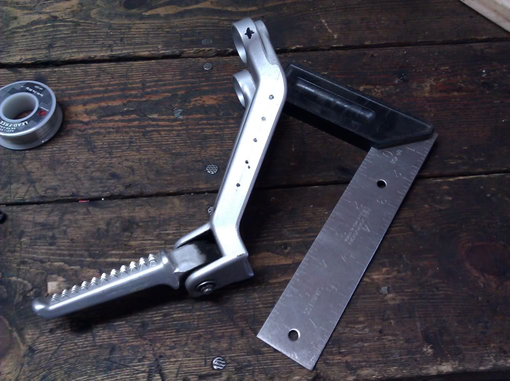
Once your measuring is complete, place peg in a vice. I used a punch tool to start all of the holes and decrease the chance of the drill bit traveling.
Choosing the proper size drill bit will depend upon the size of the LED and housing if you choose to use one. I did use a housing and recommend that you do. They are cheap. It is basically a plastic sleeve and the LED goes inside. This makes for easier removal at a later time if the light needs to be replaced.
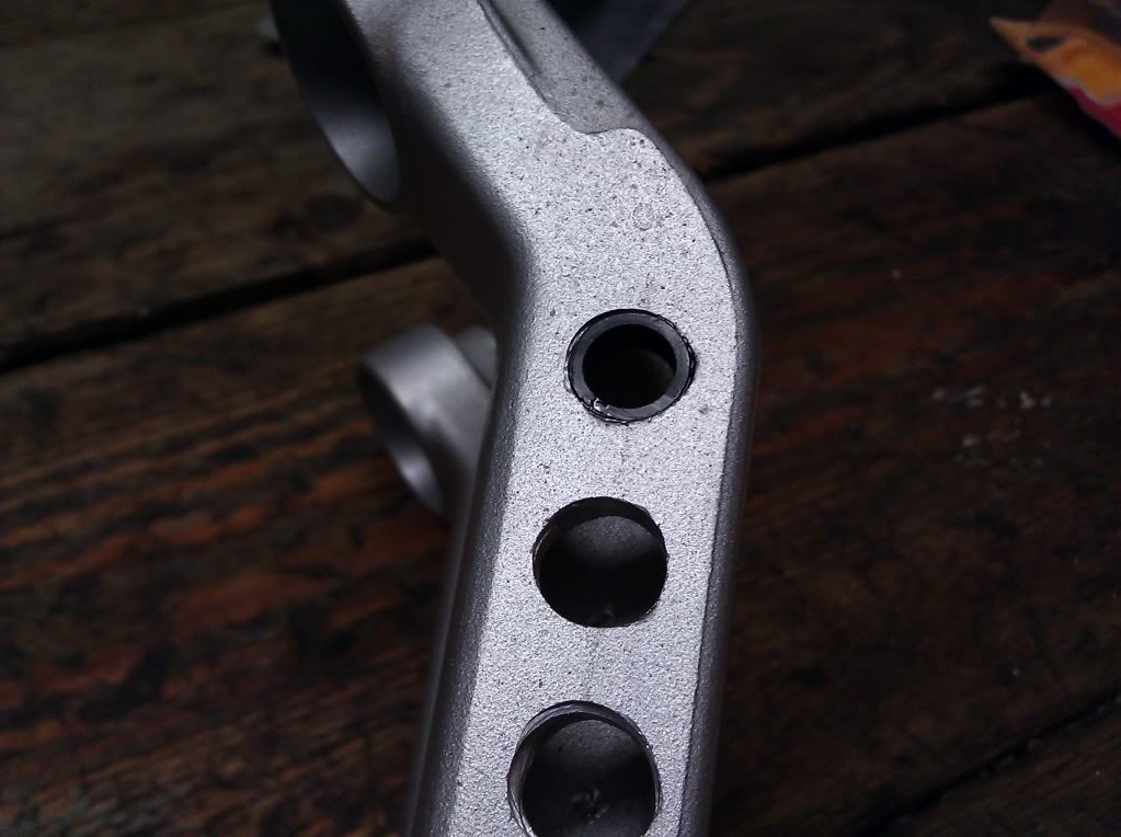
Begin drilling.
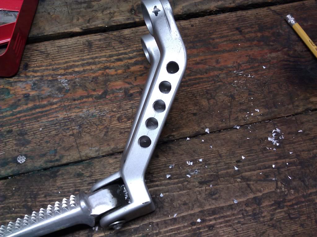
As you can see above, my bit traveled slightly on a few of the holes. I'm a novice and it's something that could be approved upon. In reality once the pegs are on the bike you can't tell in the slightest.
Once all holes are drilled. Start placing plastic sleeves into holes. You want an even fit. If it is too snug the LED will be squeezed inside the sleeve and has a risk of breaking/getting damaged.
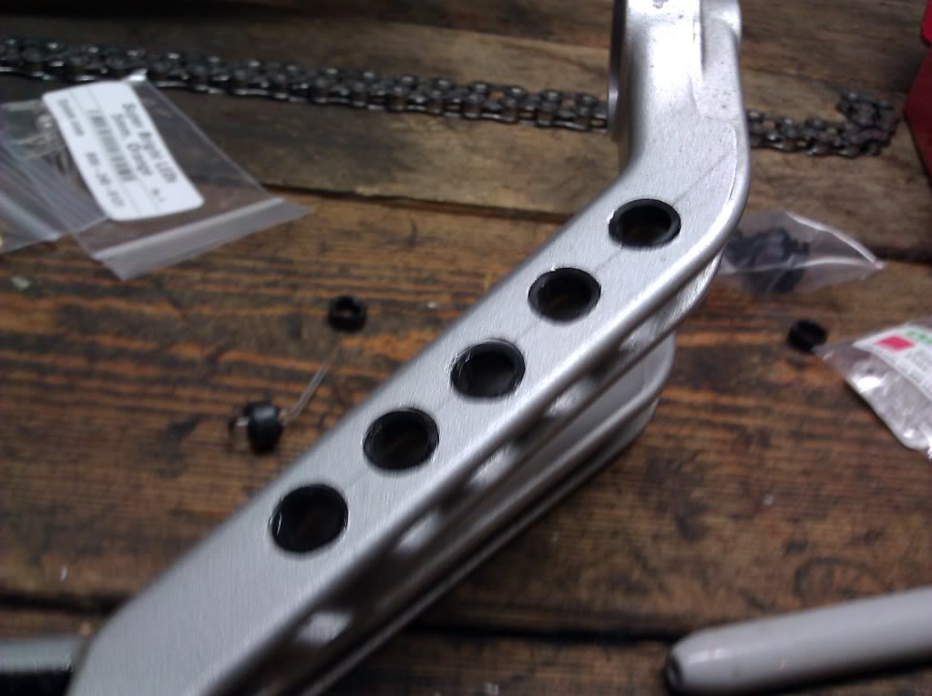
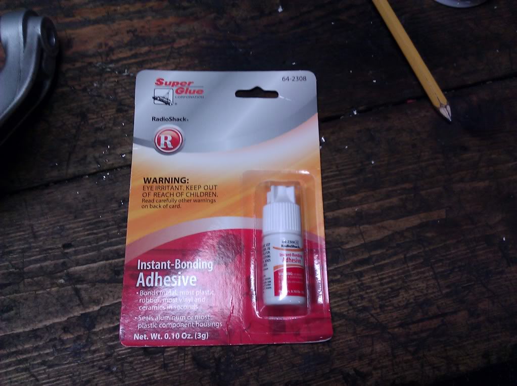
I drilled the holes so the sleeves did not fit tight. They were snug enough not to fall out, but they needed to be glued in place. I purchased superglue from radio shack and lightly glued each sleeve in place.
Once holes are drilled and sleeves are placed. You are ready to move onto step two.
STEP TWO: WIRING
As I said before, I chose to use 5mm LEDS. I purchased my LEDS and plastic sleeves from: http://www.oznium.com/leds
I bought the LEDS as components and did all the wiring myself. You will need to purchase resistors since you are pulling power from 12v. If you do not use resistors it will blow all of the bulbs. Don't worry, resistors are no big deal and they are cheap. I purchased my resistors from: http://www.oznium.com/leds I have no affiliation with this company. I am please with their product however.
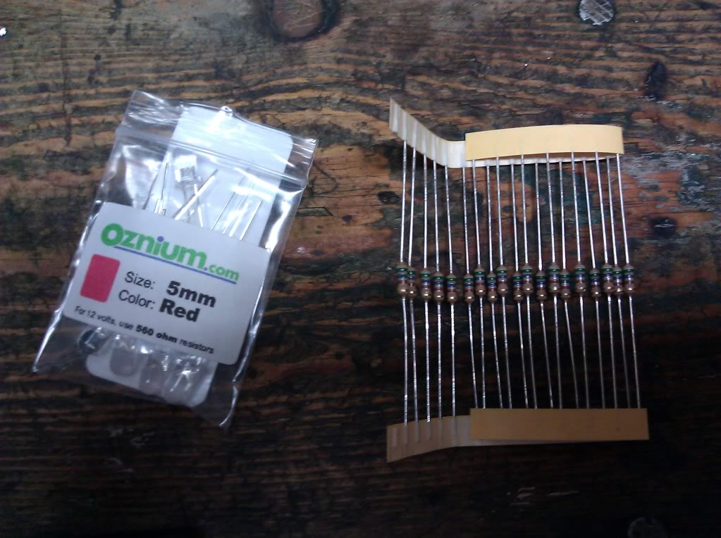
To determine which resistors you will need, refer to this guide: http://www.superbrightleds.com/cgi-b...2Fled_info.htm
I soldered all my wires and I recommend that you do too. I went out and bought a cheep soldering iron from radio shack and some cheap solder. I've done little to no soldering in my life. If you are in the same boat... do yourself a 5 minute favor and watch this: http://www.youtube.com/watch?v=BLfXXRfRIzY
Time to begin!
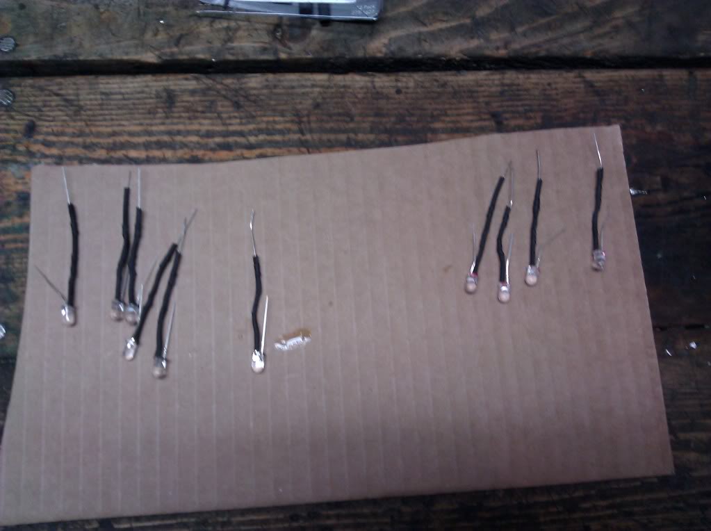
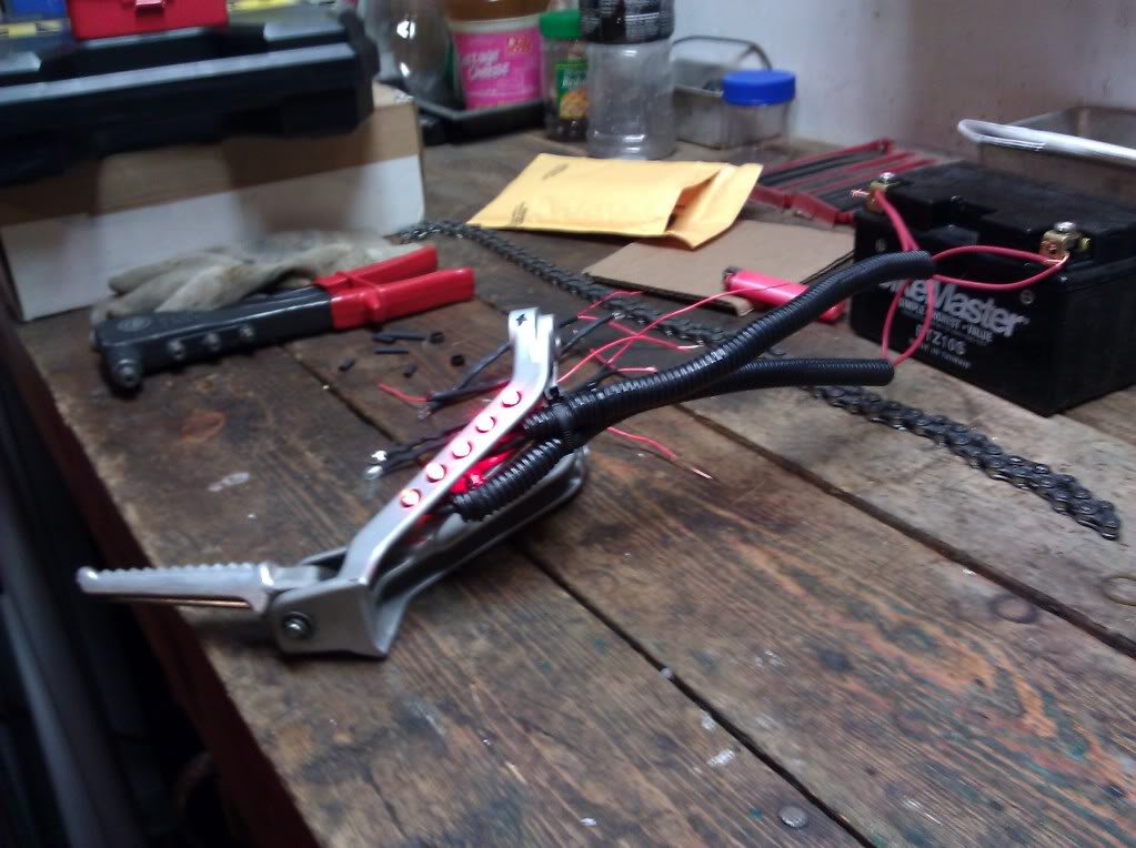
I wired 6 Red LEDS and 4 Amber LEDS. Prior to wiring anything, mark which bulb is red and which one is amber. This is VERY important for organizational purposes and will help you later on when they all mix together. I attached a resistor to each bulb. Make a good physical connection by twisting the positive end of the LED to the resistor.
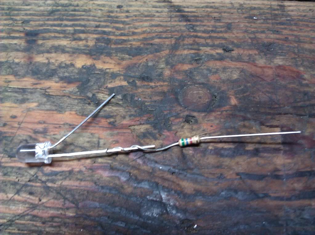
Now solder!
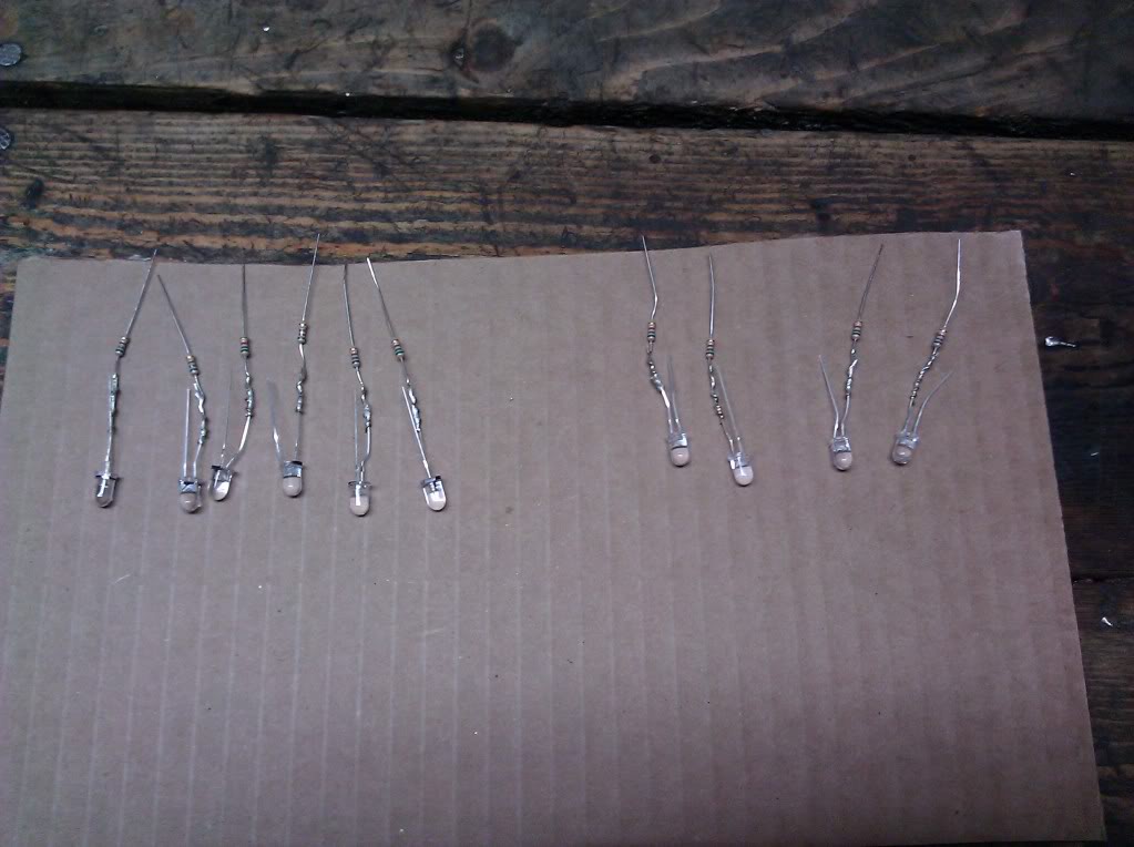
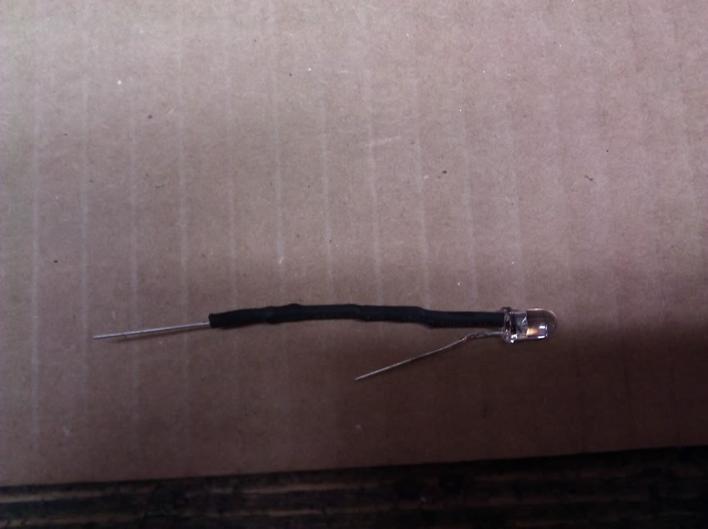
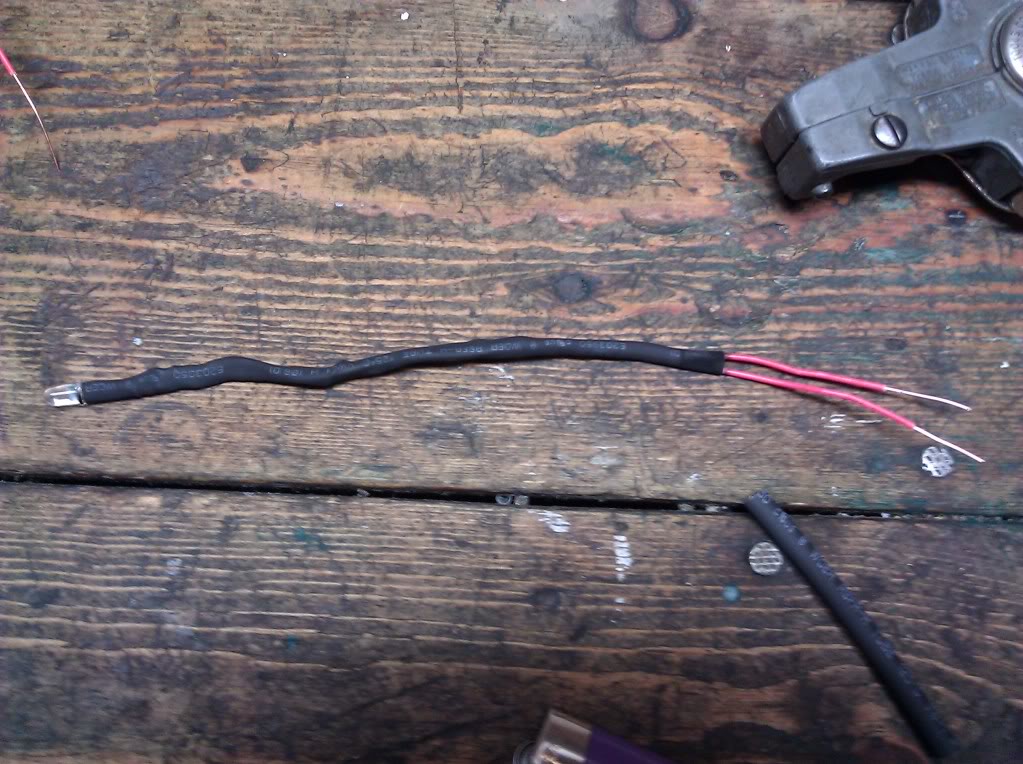
Next I heat shrunk the positive end of the LED.
Next, string out 20 similar length pieces of wire.
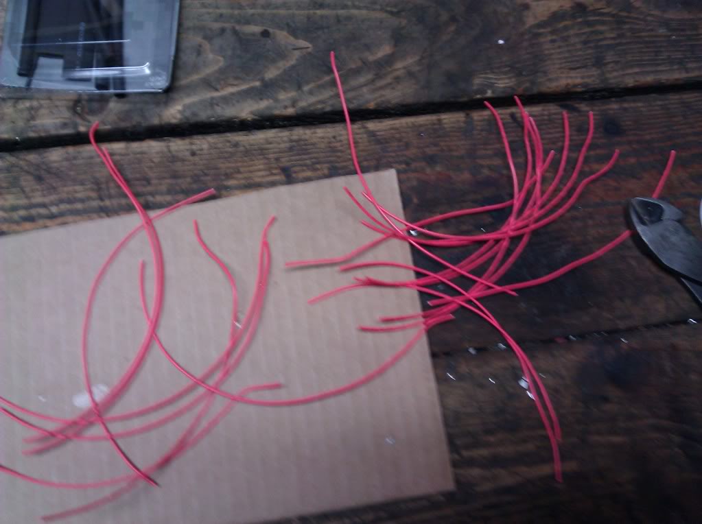
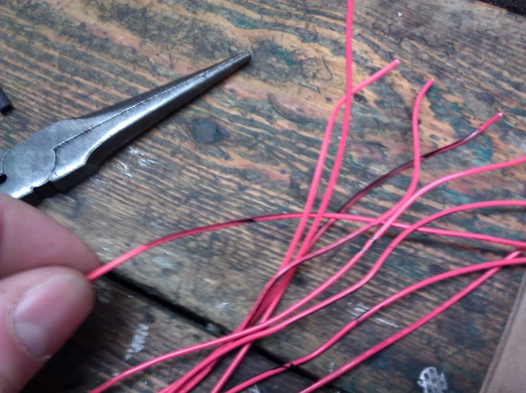
You can either use Black/Red wire (for positive and ground) or you can make the ground wires with black marker, which is what I did. This becomes very important later on for organizational purposes. (See above)
Solder 1 positively marked wire to the positive end of the resistor using good soldering techniques. Solder 1 ground marked wire to the negative end of the LED.
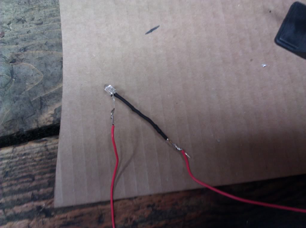
Now heat shrink together. Do the same for all 10 bulbs.
After wiring all 10 bulbs, pull out the battery and test each one to make sure that all work correctly.
After testing you are ready for next step.
STEP THREE: Installation
When I ordered my plastic sleeves, they came with a plastic housing that the LED snapped into. Then plastic housing then snapped into the plastic sleeve that was placed in the peg. Sorry no pics of that.
Place wired LED into the plastic housing. I put some light superglue on the plastic housing and then snapped it into the sleeve that was already glued into the peg. If I were to do this project again I would rethink this step. It worked but the glue became a bit of a mess and I got some of it on the LED bulbs. It wasn't a big deal and did not effect the brightness. However, I did spend 2 days scrubbing the glue off my fingers. Maybe you guys are a bit more coordinated than I am Overall, it worked just fine and the sleeves, housings, and LEDS were securely in place after the glue dried.
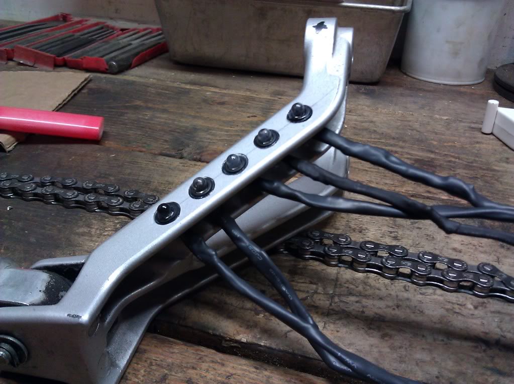
Next, string out more wire and cut to desired length. Combine ALL positive wires and negative wires coming from your bulbs. Solder 1 main positive and 1 main negative wire. You should now have 2 wires coming from your peg. 2 Positives and 2 negatives. Heat shrink over all the connection points.
Next, pull that battery out and retest everything. If a bulb doesn't work, you'll have to retrace the wiring and figure out where the problem is. If you properly marked all the positive and negative wires, and connected them properly using solid soldering techniques you will NOT have a problem. When I tested mine they all worked.
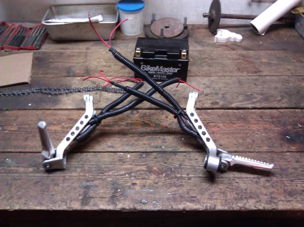
At this point, I decided to put some plastic wire conduit over all the wiring to help protect it from the elements. Utilize tie straps to help secure everything.
Now, retest everything. It is much easier to retrace mistakes sooner than later.
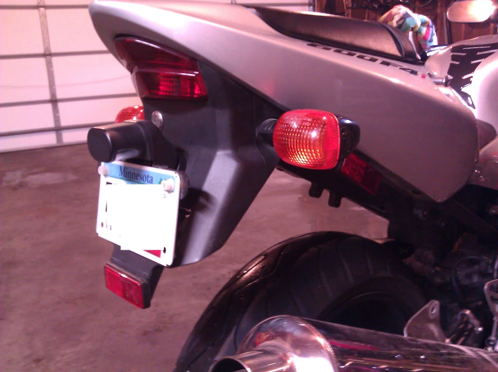
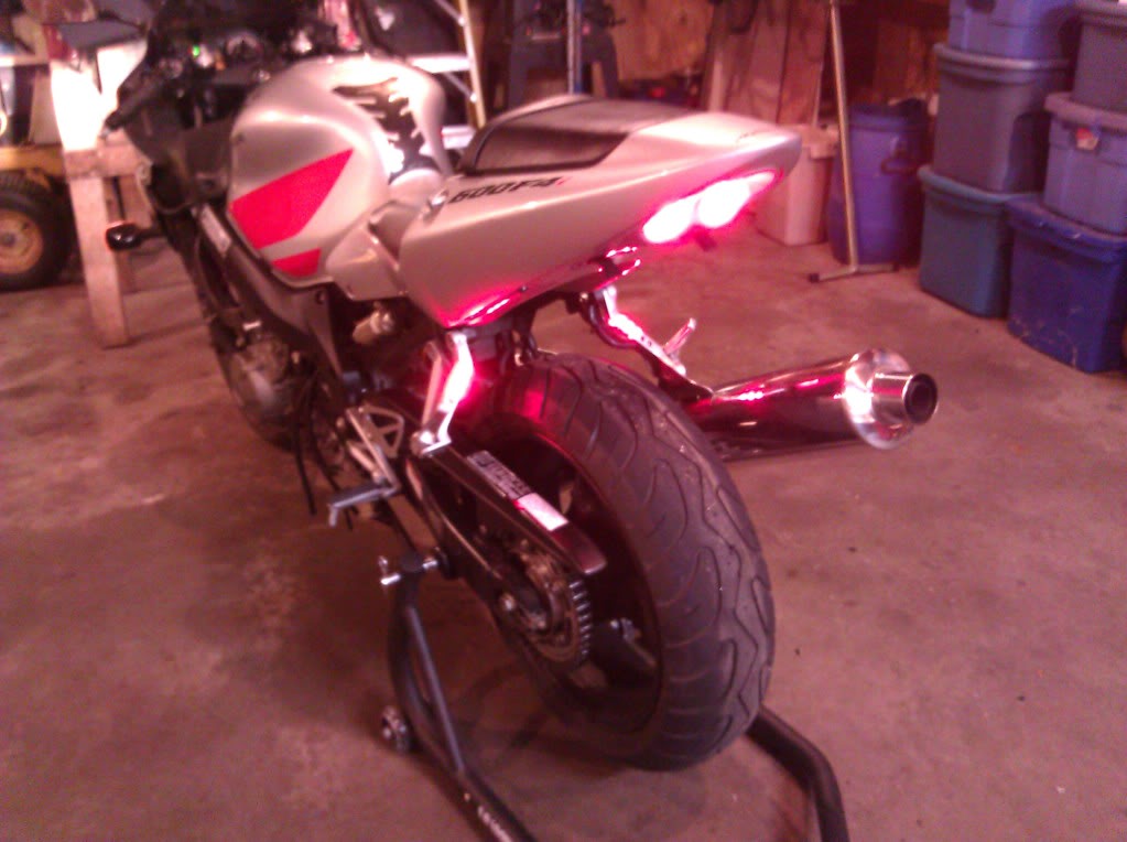
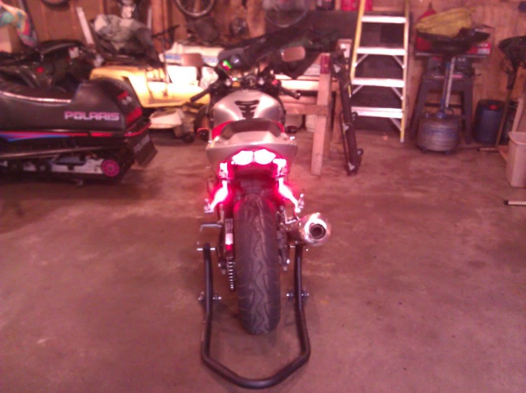
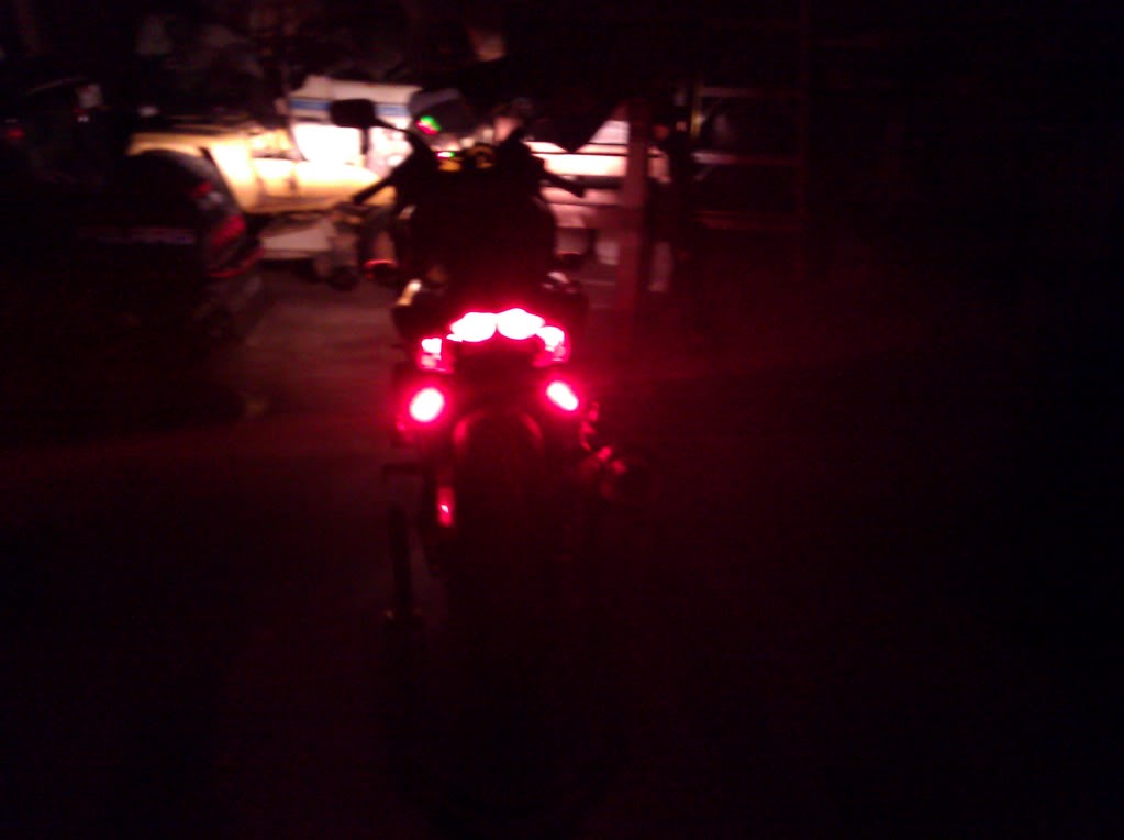
You also get to see just how bright they lights now are. This crappy phone photo does not do it justice. Also keep in mind the lights are directional. So everyone traveling behind you is going to get the full blast. I was VERY pleased with how bright these 8,000 mcd lights were.
When I tested my bulbs at this point, I found 1 not working. Turns out a negative leed had disconnected from a bulb due to the bending I did to get all the wires in place. Easy enough to fix at this point. I wired up a replacement bulb and reattached. No problem.
STEP FOUR: CONNECTION TO BIKE
Since I ordered and was installing a Hotbodies undertail. I connected everything at the same time. Everyones wiring at this point may be a bit different.
First I installed the pegs back into the bike. I used tie straps to place the peg LED wires where I wanted them. I fished them to the back of the bike where I would be connecting them to the stock tail light/blinker wiring.
I did string out and measure more wire that I connected to the passenger peg leds. The wires that I had already connected would not reach back to the stock wiring in the undertail. No big deal, I just soldered and heat shrinked everything together.
Next I connected all the wiring from the undertail to the stock wiring. I followed the Hotbodies instructions, which were poor at best.
After connecting everything up I connected my LED peg wiring to the hotbodies/stock wiring I had just completed.
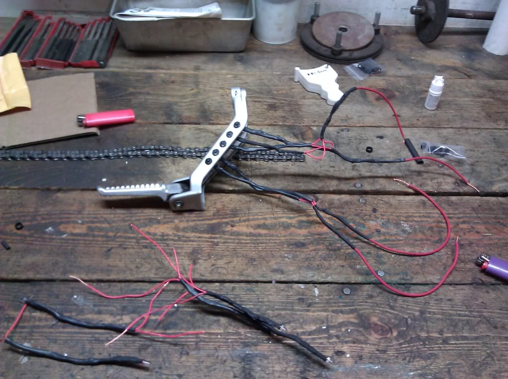
It does become quite a wiring mess. An that reinforces the need to either use red/black wires to denote positive and negative. Or, mark all the negative wires with a marker as I did.
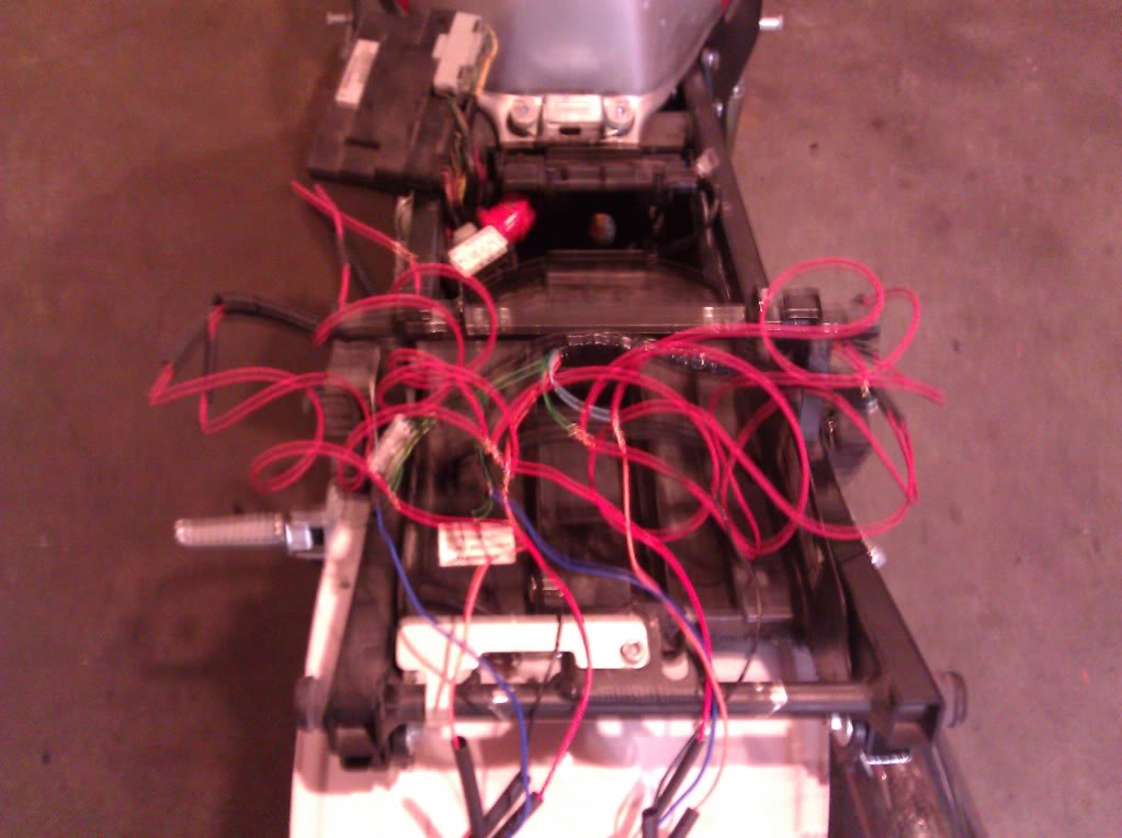
It looks much worse than it is. I connected EVERYTHING by twisting wires and DID NOT SOLDER yet. I tested the connections. They all worked. I went ahead and soldered and heat shrunk everything.
I then organized all the wires using tie straps and placed them around the frames as to not obstruct the use of the glove box.
YOUR DONE!
Before
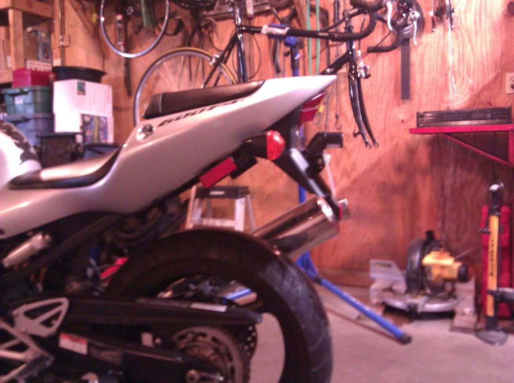
After
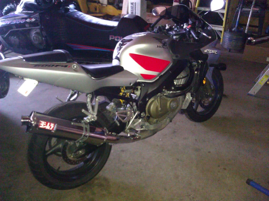
After Hotbodies Undertail, LED PEG Installation, and Yoshimura TRS Installation
Conclusion:
It took me about 18 hours to do all the above work including undertail and exhaust. I am VERY pleased. The LED's in the pegs improves visibility drastically and as we all know, on a motorcycle that is crucial to safety. It also looks fantastic. I apologize for the less than stellar camera phone pictures but I think you get the idea. PM or reply for any questions. Thanks
This is my first post; however, I've lurked for quite some time. This winter I decided to begin a few projects on my 02 CBR 600 F4i. I ordered a Hotbodies undertail kit and Yoshimura TRS s/s slip on. After doing some research I came to the conclusion that the stock LED break/turn signals in the Hotbodies undertail were not going to satisfy my safety standards. For those that don't know the Hotbodies undertail stock tail light does decrease visibility from rear in comparison to the stock tail light. My way to remedy the situation was to add passenger peg LED tail lights and turn signals. It turned out great.
Here is what my bike looked like before I started any mods.
This guide will focus mostly on the LED Tail lights. However, I'll add in notes on the undertail installation and the exhaust installation. With pics of course!
STEP 1: Pegs
Decide what type of LED set up you want. You can basically do whatever you want with as many lights as you want. I decided to add 5 lights to each side. The top 3 are wired as break lights and are red. The bottom 2 are amber turn signals and are wired as such.
Decide on the type of LED you wish to use. I ordered 5mm 8,000 MCD LEDS with a 30 degree viewing angle. They are visually directional so keep that in mind.
Remove the passenger pegs. Make sure to mark which one is right and left. Believe me, you do not want to be drilling holes on the wrong side of the peg. Which can easily happen when you get a workbench full of tools/parts.
As for measuring. I suck. I can admit that. I measured out and found the centerline of the peg. I then measured 1.5 cm intervals for hole drilling.
Once your measuring is complete, place peg in a vice. I used a punch tool to start all of the holes and decrease the chance of the drill bit traveling.
Choosing the proper size drill bit will depend upon the size of the LED and housing if you choose to use one. I did use a housing and recommend that you do. They are cheap. It is basically a plastic sleeve and the LED goes inside. This makes for easier removal at a later time if the light needs to be replaced.
Begin drilling.
As you can see above, my bit traveled slightly on a few of the holes. I'm a novice and it's something that could be approved upon. In reality once the pegs are on the bike you can't tell in the slightest.
Once all holes are drilled. Start placing plastic sleeves into holes. You want an even fit. If it is too snug the LED will be squeezed inside the sleeve and has a risk of breaking/getting damaged.
I drilled the holes so the sleeves did not fit tight. They were snug enough not to fall out, but they needed to be glued in place. I purchased superglue from radio shack and lightly glued each sleeve in place.
Once holes are drilled and sleeves are placed. You are ready to move onto step two.
STEP TWO: WIRING
As I said before, I chose to use 5mm LEDS. I purchased my LEDS and plastic sleeves from: http://www.oznium.com/leds
I bought the LEDS as components and did all the wiring myself. You will need to purchase resistors since you are pulling power from 12v. If you do not use resistors it will blow all of the bulbs. Don't worry, resistors are no big deal and they are cheap. I purchased my resistors from: http://www.oznium.com/leds I have no affiliation with this company. I am please with their product however.
To determine which resistors you will need, refer to this guide: http://www.superbrightleds.com/cgi-b...2Fled_info.htm
I soldered all my wires and I recommend that you do too. I went out and bought a cheep soldering iron from radio shack and some cheap solder. I've done little to no soldering in my life. If you are in the same boat... do yourself a 5 minute favor and watch this: http://www.youtube.com/watch?v=BLfXXRfRIzY
Time to begin!
I wired 6 Red LEDS and 4 Amber LEDS. Prior to wiring anything, mark which bulb is red and which one is amber. This is VERY important for organizational purposes and will help you later on when they all mix together. I attached a resistor to each bulb. Make a good physical connection by twisting the positive end of the LED to the resistor.
Now solder!
Next I heat shrunk the positive end of the LED.
Next, string out 20 similar length pieces of wire.
You can either use Black/Red wire (for positive and ground) or you can make the ground wires with black marker, which is what I did. This becomes very important later on for organizational purposes. (See above)
Solder 1 positively marked wire to the positive end of the resistor using good soldering techniques. Solder 1 ground marked wire to the negative end of the LED.
Now heat shrink together. Do the same for all 10 bulbs.
After wiring all 10 bulbs, pull out the battery and test each one to make sure that all work correctly.
After testing you are ready for next step.
STEP THREE: Installation
When I ordered my plastic sleeves, they came with a plastic housing that the LED snapped into. Then plastic housing then snapped into the plastic sleeve that was placed in the peg. Sorry no pics of that.
Place wired LED into the plastic housing. I put some light superglue on the plastic housing and then snapped it into the sleeve that was already glued into the peg. If I were to do this project again I would rethink this step. It worked but the glue became a bit of a mess and I got some of it on the LED bulbs. It wasn't a big deal and did not effect the brightness. However, I did spend 2 days scrubbing the glue off my fingers. Maybe you guys are a bit more coordinated than I am
Next, string out more wire and cut to desired length. Combine ALL positive wires and negative wires coming from your bulbs. Solder 1 main positive and 1 main negative wire. You should now have 2 wires coming from your peg. 2 Positives and 2 negatives. Heat shrink over all the connection points.
Next, pull that battery out and retest everything. If a bulb doesn't work, you'll have to retrace the wiring and figure out where the problem is. If you properly marked all the positive and negative wires, and connected them properly using solid soldering techniques you will NOT have a problem. When I tested mine they all worked.
At this point, I decided to put some plastic wire conduit over all the wiring to help protect it from the elements. Utilize tie straps to help secure everything.
Now, retest everything. It is much easier to retrace mistakes sooner than later.
You also get to see just how bright they lights now are. This crappy phone photo does not do it justice. Also keep in mind the lights are directional. So everyone traveling behind you is going to get the full blast. I was VERY pleased with how bright these 8,000 mcd lights were.
When I tested my bulbs at this point, I found 1 not working. Turns out a negative leed had disconnected from a bulb due to the bending I did to get all the wires in place. Easy enough to fix at this point. I wired up a replacement bulb and reattached. No problem.
STEP FOUR: CONNECTION TO BIKE
Since I ordered and was installing a Hotbodies undertail. I connected everything at the same time. Everyones wiring at this point may be a bit different.
First I installed the pegs back into the bike. I used tie straps to place the peg LED wires where I wanted them. I fished them to the back of the bike where I would be connecting them to the stock tail light/blinker wiring.
I did string out and measure more wire that I connected to the passenger peg leds. The wires that I had already connected would not reach back to the stock wiring in the undertail. No big deal, I just soldered and heat shrinked everything together.
Next I connected all the wiring from the undertail to the stock wiring. I followed the Hotbodies instructions, which were poor at best.
After connecting everything up I connected my LED peg wiring to the hotbodies/stock wiring I had just completed.
It does become quite a wiring mess. An that reinforces the need to either use red/black wires to denote positive and negative. Or, mark all the negative wires with a marker as I did.
It looks much worse than it is. I connected EVERYTHING by twisting wires and DID NOT SOLDER yet. I tested the connections. They all worked. I went ahead and soldered and heat shrunk everything.
I then organized all the wires using tie straps and placed them around the frames as to not obstruct the use of the glove box.
YOUR DONE!
Before
After
After Hotbodies Undertail, LED PEG Installation, and Yoshimura TRS Installation
Conclusion:
It took me about 18 hours to do all the above work including undertail and exhaust. I am VERY pleased. The LED's in the pegs improves visibility drastically and as we all know, on a motorcycle that is crucial to safety. It also looks fantastic. I apologize for the less than stellar camera phone pictures but I think you get the idea. PM or reply for any questions. Thanks
Last edited by FAEL0401; Feb 20, 2011 at 05:33 PM.

Thread Starter
|
Junior Member
Joined: Feb 2011
Posts: 7
Likes: 1
From: Minneapolis, MN
No I did not. It may be something I would consider in the future if ever doing this again. Also, I would have wired the 3 break lights in a series. It would have eliminated a few wires. After organizing all the wires and strapping them around the outside of the tail frame the mess was mostly contained. I included picture of the wires all jumbled together to reinforce the need for organization. It wasn't nearly that bad after everything was put in place and can't be seen unless you take the tail section off

very nice job.....
wiring LEDs is not as complicated as i thought it would be.
i have few ideas i want to do, but making a brake light into a peg is a great safety idea.
i might just copy you and make it a project for me.
how much was the total for all the components. it couldnt be to much.
thx for the walk throgh and the pics. that helps a lot.

Junior Member
Joined: Apr 2010
Posts: 6
Likes: 0
From: Sheboygan, WI
Awesome project! props for taking your time to do it right! i took the easy route and got LED strips at autozone... works wonders and can be trimmed to exact length needed....
http://www.google.com/imgres?imgurl=...1t:429,r:3,s:0
http://www.google.com/imgres?imgurl=...1t:429,r:3,s:0
Thread Starter
|
Junior Member
Joined: Feb 2011
Posts: 7
Likes: 1
From: Minneapolis, MN
very nice job.....
wiring LEDs is not as complicated as i thought it would be.
i have few ideas i want to do, but making a brake light into a peg is a great safety idea.
i might just copy you and make it a project for me.
how much was the total for all the components. it couldnt be to much.
thx for the walk throgh and the pics. that helps a lot.
wiring LEDs is not as complicated as i thought it would be.
i have few ideas i want to do, but making a brake light into a peg is a great safety idea.
i might just copy you and make it a project for me.
how much was the total for all the components. it couldnt be to much.
thx for the walk throgh and the pics. that helps a lot.
I want to say the entire project set me back about 50$. That includes the soldering iron, solder, other tools, etc. I also purchased extra wire and bulbs in the case I need to replace a bulb in the future.
what size wire did you use.
i looked at radio shack LEDs and they didnt have anything good and it was expensive. so ill use that sight to get the LEDs and the resistors.
the only things i got from radio shack was the heat shrinks, LED holders, and the glue that you used.
ill take the foot pegs off today and drill the holes. i want to be ready for the when the lights come in.
i need to buy the wire and the plastic tubes to hide the wires.
Thread Starter
|
Junior Member
Joined: Feb 2011
Posts: 7
Likes: 1
From: Minneapolis, MN
I believe I used 22 gauge wire for the wiring at the LEDS. At the points where all the lights merged I used 18 gauge wire. Power going to LEDS is pretty light. I think using the 22 the whole way would have been fine. It doesn't matter much.
