When you click on links to various merchants on this site and make a purchase, this can result in this site earning a commission. Affiliate programs and affiliations include, but are not limited to, the eBay Partner Network.
Probably just part of cable-run in harness from ignition-unit. That brought them up right side of bike.
Yup, those blu/yel and yel/blu wires look like triggers for coils. Not sure why they're not connected to anything. Trace those wires back from coils and see if they're disconnected from other end too!
Do you know what the impedance is of those sticks? The coils on the 1000F were 2.6 - 3.2 Ω.
Originally Posted by MN Hurricane
When I checked the ohms each coil was 1.6
the base ohms of the leads were showing .3
if my math is right 1.6-.3 would give me 1.3 per stick
This is typically why you run power with 2 sticks in series, so they appear to ignitor as single 2.6ohm coil. Been many cases where extra draw from lower-impedance coil causes overheating and failure of ignition unit. Typically starts out as high-RPM misfire and stumbling. Which starts earlier and earlier in RPM range. Eventually ignition dies completely.
Thanks I appreciate your help, but if you could please dumb it down for me…😊
does this mean that I don’t have the correct wiring on the coils? Oh yeah, and do I really need that relay since I have no fuel pump?
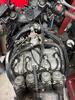
An update to share…I removed the tape on the relay that was in the approximate area where the fuel pump would have been installed. This red wire was grounded to the battery I removed a bunch of electrical tape and found a few things. Purple circle is the wire that was grounded Green circle was just hanging out at the front of the bike, maybe an in-line fuse? Orange circles are two cut off wires (These look important)
I hope this is helpful in figuring out the situation.
This is great! That's not original fuel-pump relay, which is rectangular with 2-wire connector. Remove that relay and all attached wires. Note which harness wires they were attached to, then disconnect and cover up wound in original wiring.
In last photo, is that wire with ring-terminal showing some bubbling and melted insulation?
Not able to figure how those coils are connected. Can you untape and spread out wires? I'm working up diagram of how those stick coils should be wired. Then you can compare with what you have.
remember: There never seems to be enough time to do job right 1st time around. But there's ALWAYS time to do it again!! Often times on side of road in total darkness and rain!!!
and to add to that ... with your wife yelling I told you so!
I checked those two coil wires and found that they do indeed have power running to them. 🤦🏻 With the key on but .5-.10 volts with the stop switch on.
Are you taking about blu/yel and yel/blu wires in back not connected to anything? Those are ground wires for coil circuit. Remember how you had already measured 11.65v at coils themselves? The other side of that circuit has to be ground for current to flow. So ignitor grounds those blu/yel and yel/blu wires to flow current through coil from blk/white wires.
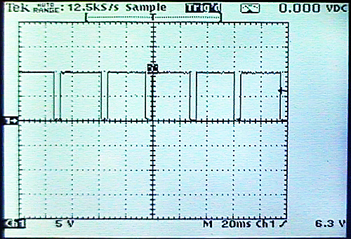
Can't measure ground pulses with voltmeter. You can connect 'noid light which will blink when there's grounding pulses. Or use oscilloscope:
Coils have power full-time by default. Then for short time segment, ignitor grounds other side of primary to dump magnetic-field and fire plugs.


 08-24-2022 | 06:53 PM