

Accessories loom.
#1
 09-20-2013, 03:30 AM


Join Date: Apr 2013
Location: Edinburgh, Scotland
Posts: 37
Likes: 0
Received 0 Likes
on
0 Posts
So, I am about to embark on version 3 of my exciting accessories loom (on a cbr600 '95 F3), and thought I'd share my experiences and also see if any electronics experts can tell me why i've failed so far (I have my guesses, but confirmation would be nice)
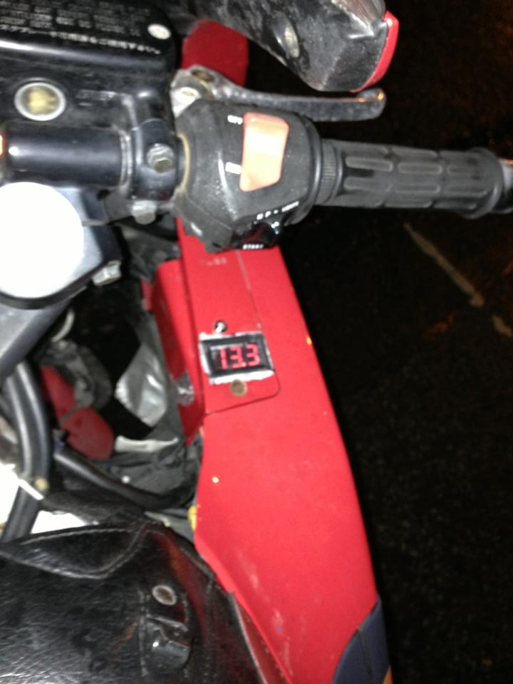
I had previously built a voltage monitor onto the bike (very simple circuit - pos battery terminal > inline fuse > on off switch > voltage monitor > neg battery terminal) Very simple, but it was my first one and I was proud!
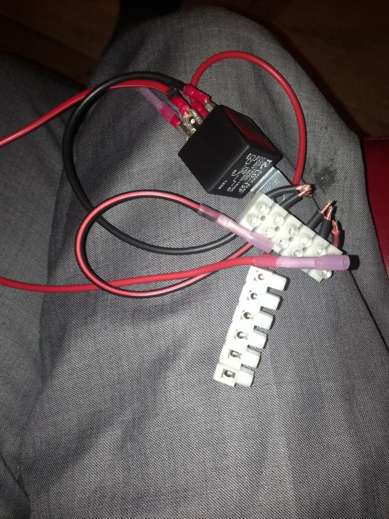
So I built an accessories loom (which I probably could have bought a 'fink' one for easiness and probably cheaper than my parts list, but I'm stubborn and like to figure things out myself)
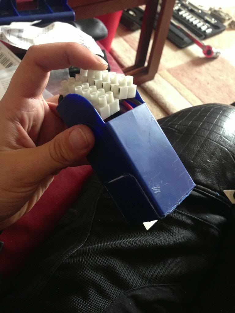
I thought it looked pretty good considering it came from an old desk-stationary holder!
Tested it on spare battery and it worked perfect so set about attaching to bike. Unsuccesfully. Twice. So far.
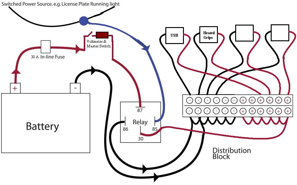
Attempt 1:
With this, the accessories loom worked perfectly, but my voltmeter wouldn't do a thing.
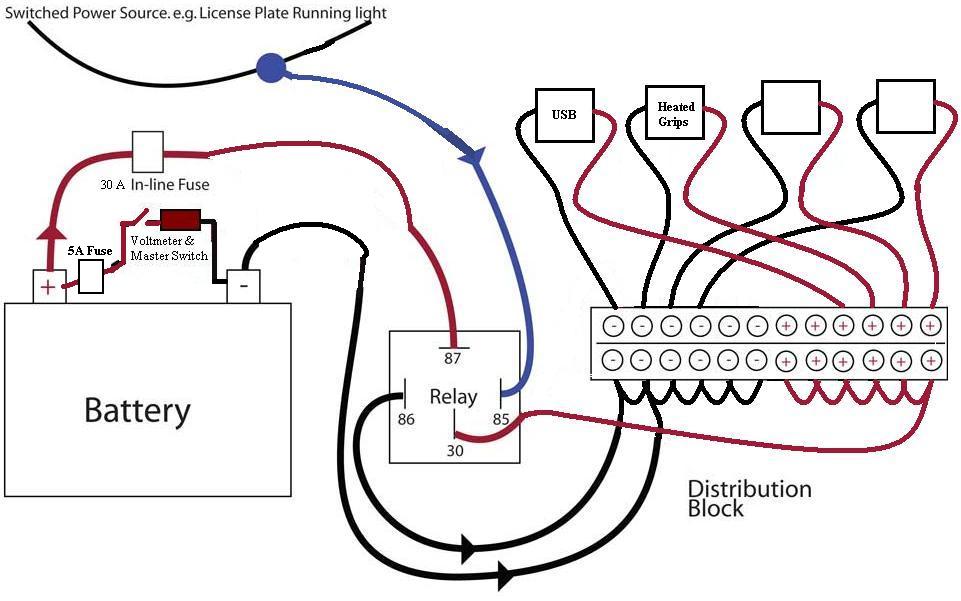
So I tried Attempt 2:
In this case, my voltmeter was back up and running! hurrah! But there was no power from the outputs of the accessories loom.
Well, I say no power, actually they were showing about 0.3v, same as the voltmeter showed in attempt 1, but that wasn't enough to turn it on at all. So I'm guessing some power bleeding through, but not enough.
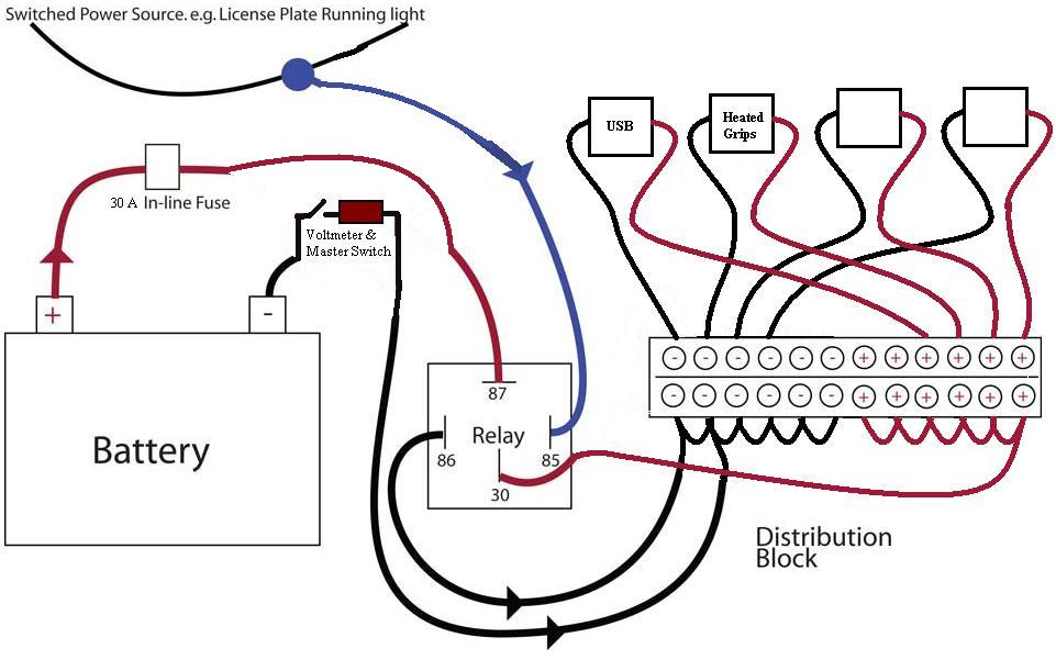
So tonight, (or maybe next week) I will go for attempt 3:
Any smart people wanna tell me wrong.
Any gamblers wanna place bets on how many more attempts it will take me?
I had previously built a voltage monitor onto the bike (very simple circuit - pos battery terminal > inline fuse > on off switch > voltage monitor > neg battery terminal) Very simple, but it was my first one and I was proud!
So I built an accessories loom (which I probably could have bought a 'fink' one for easiness and probably cheaper than my parts list, but I'm stubborn and like to figure things out myself)
I thought it looked pretty good considering it came from an old desk-stationary holder!
Tested it on spare battery and it worked perfect so set about attaching to bike. Unsuccesfully. Twice. So far.
Attempt 1:
With this, the accessories loom worked perfectly, but my voltmeter wouldn't do a thing.
So I tried Attempt 2:
In this case, my voltmeter was back up and running! hurrah! But there was no power from the outputs of the accessories loom.
Well, I say no power, actually they were showing about 0.3v, same as the voltmeter showed in attempt 1, but that wasn't enough to turn it on at all. So I'm guessing some power bleeding through, but not enough.
So tonight, (or maybe next week) I will go for attempt 3:
Any smart people wanna tell me wrong.
Any gamblers wanna place bets on how many more attempts it will take me?
#2
09-20-2013, 06:14 AM
I dont see why the third one wont work as you intend. Looks like alot of wires to me. Are you getting enough power to every output on your power distribution? I usually get a marine terminal that has a signal input and multiple outputs with the fuses built in. Similar to the ones for car stereo amps but with micro fuses instead of the huge fuses. I would imagine in your previous design the voltmeter was causing your issues. Anyway, let us know what happens. I like the idea of the voltmeter though. May have to swipe the idea
#3
09-20-2013, 11:42 AM

Track junkie & modaholic
Join Date: Aug 2011
Location: USA
Posts: 1,847
Likes: 0
Received 0 Likes
on
0 Posts
#4
10-07-2013, 05:44 PM
Join Date: Apr 2013
Location: Edinburgh, Scotland
Posts: 37
Likes: 0
Received 0 Likes
on
0 Posts
#5
10-08-2013, 09:10 PM

Senior Member
#6
10-08-2013, 09:23 PM


Thread
Thread Starter
Forum
Replies
Last Post