When you click on links to various merchants on this site and make a purchase, this can result in this site earning a commission. Affiliate programs and affiliations include, but are not limited to, the eBay Partner Network.
I really value the help, so thank you very much for it!
This is teaching me a lot.
You're right; to identify the issue, I should conduct appropriate testing and measurement. I should have done it right away, but hey, there's always a first time.
Though it has been some time, I have returned the original parts as you advised.
I don't currently have access to a good oscilloscope. I'm going to purchase one. Do you have any suggestions on which one to get?
I checked the following: 1. Are you still getting error code 7 & 8??? Never provided any numbers from their testing. I forgot to verify this. I'll check on Wednesday! 2. Were camshafts ever removed to adjust valve-clearance? Valve clearance has been adjusted once before. This was done 2,5 years ago.
Use wiring-diagram and confirm colours of wires going into every sensor. ECT and TPS uses same connectors as some others in that area and can easily get plugged in to improper location during desperate parts swapping. Better to make list before starting. I’ll do 1st one: TPS= yel/red, grn/org, red/yel IAT= grey/blue, green/ orange MAP= yellow/red, green/orange, licht green/yellow ECT= Pink/white, green/orange, green/blue CKP= Yellow, Yellow/White CMP= Dark grey, light grey BAS= green, white/black, red/orange VSS= Pink, green, black
I will check if this corresponds with the wiring diagram stated in the workshop manual.
Do following measurements. 1. with everything OFF, measure battery power, volts=12.75V 2. key ON, start/stop=RUN, measure battery power, volts= 12.60V 3. measure battery power during cranking, volts=10.52V
Following are ONLY things that tells ECU to not fire sparks, even though it does pump-prime. Disconnect ECU from harness-connector:
This is were I got very weird readings. I checked with 2 other [size=13px]multimeter's[/size] but got the same values. 4. at ECU connector, measure resistance between grn/wht wire and chassis-ground. ohms =2M ohms to 20M ohms (maxed out the meter on 20.000.000 ohms) 5. at ECU connector, measure resistance between grn/red wire and chassis-ground, ohms =3M ohms to 11M ohms.
Instead of receiving a single number, the values were changing every second.
I can share a video of this with you later if you would like.
These numbers should tell us what's wrong and how to fix it. I would really like to know what that means.
These cables, if my understanding is correct, go to the clutch switch.
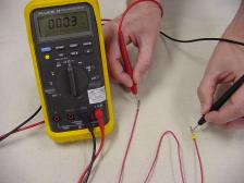
I thus used the multimeter in "beep" mode to see if I had a closed circuit from the ecu to the switch, and back.
It does indeed beep.
I'm having trouble understanding why my resistance values are so high.
Thank you for any extra help in advance!
I'll follow the other instructions you provided.
Simply put, I did not have enough time to complete everything.
I'm hoping to acquire a decent oscilloscope by this Wednesday.
No oscilloscope necessary, we’ve found problem! For future learning, you can get cheap “USB pocket scope”. These are simple devices which uses software and processing power of modern laptops or phones to replace lots of hardware found in older scopes.
Now that you have plug colours defined, go to bike and verify proper plugs are connected to each sensor.
We’ve narrowed down problem areas:
1. Low battery - not enough power during cranking to run ECU and fire sparks. You have same problem as disconnecting and removing ECU from bike. No spark!
Do following measurements.
1. with everything OFF, measure battery power, volts= 12.75V
2. key ON, start/stop=RUN, measure battery power, volts= 12.60V
3. measure battery power during cranking, volts= 10.52V
Put battery on smart-charger for at least 24-hrs. Want >13,5v fresh off charger. And most important, >11,0v during cranking.
2. Safety interloc circuits not working. ECU thinks there’s unsafe condition and won’t fire sparks. This is same as putting down sidestand when engine’s running, ECU will kill spark and stop engine.
This is were I got very weird readings. I checked with 2 other [size=13px]multimeter's[/size] but got the same values.
4. at ECU connector, measure resistance between grn/wht wire and chassis-ground. ohms = 2M ohms to 20M ohms (maxed out the meter on 20.000.000 ohms)
5. at ECU connector, measure resistance between grn/red wire and chassis-ground, ohms = 3M ohms to 11M ohms.
Instead of receiving a single number, the values were changing every second.
Very good!! High resistance readings can be caused by broken wires. They change because wires are wiggled and broken ends may meet and temporarily re-connect. Do not use continuity test, not as useful as resistance because it doesn’t give you number. Also doesn’t work across diodes, such as clutch diode. This shares line with neutral switch and diode prevents neutral globe from lighting on clocks when clutch is squeezed.
check calibration of meter - will change as batteries drain in meter
- use lowest resistance range on meter, usually 200-ohms max
- touch probe tips together, note reading you have. This should be 0,0 ohms, no resistance, control baseline measurement. If it’s not zero, remember this number as you will subtract it from all resistance-measurements you make
Put bike into neutral and squeeze clutch (strap lever to bar to keep squeezed). Then redo measurements of grn/wht & grn/red wires’ resistance to earth at ECU connector. Remember to subtract calibration offset from readings you get.
IF readings are not 0,0 zero after subtracting offset and more than 10-ohms, you’ve got corroded or broken wire or connectors issue. Measure resistance of grn/wht and grn/red wires from ECU connector to other end.
I have been busy measuring the wires.
In addition, I used the solenoid lights for the testing that you informed me of.
Regretfully, I received nothing at all! Simply put, it wouldn't blink.
We discovered that the headlight would not turn on when the key was turned when we were taking new measurements.
Only when you turn on the key and press the clutch handle will it turn on! We were astounded and about to give up.
Next, we made the decision to record the accurate voltage and resistance readings by taking some measurements from a different CBR929RR.
We discovered that all of the ground wires on my CBR929RR have 10,4V, while this is 0V on the other CBR.
Can you confirm this should be 0V on all ground wires?
We believe we have identified the origin of the 10,4V on ground wires.
Take a look at the image of the orange ground wire connector.
It is seriously broken, and we believe that a nearby 12V line is where it is receiving its voltage.
Do you consider this to be plausible?
If we pull out the IGN START 10A fuse we get only 9V on the ground wires.
If we also pull out the TURN STOP HORN PASS 10A fuse we finally get 0V on the ground wires.
Additionally, since the ECU receives the 10,4V on the ground wires, we believe it won't spark because it is clueless of what is happening.
To indicate which wire has which voltage, I have noted the measurements we have observed on the wiring schematic.
I'm going back to work at the bike on Wednesday.
Please let me know if you have any advice.
I sincerely appreciate it!
I hope you have a wonderful evening.
Cheers,
Leeroy.
Broken Orange connector
Gr/white, Gr/Red measurements. Upper (geel = mine) Below (Grijs) is the good CBR.
Note that the good CBR has no resistance while mine does have resistance.
Caused by the broken connector above?
Removing one of the Fuses that causes problem.
Measurements on wiring Diagram. (I will make a better version soon!)
ECU Connector Gr/White & Green/Red = 1,6V. Good CBR gave 5V here.
Yes, all grounds should have 0v. Something is crossed up. This is worse than we thought earlier with just disconnected or broken wire.
Zero resistance to earth of grn/wht and grn/red wire on working CBR is good! We want yours like that!
I’ll work up test-points for every circuit starting from battery and follow all junctions & branches to find where it’s crossed up. Should be ZERO connection between clutch and kill-switch and power anywhere.
Orange cap covers multi-point connections to earth. Take cap off and clean corrosion off all terminals. Use sandpaper, contact-cleaner, etc. Some people have had good luck soldering all terminals to common metal bar to prevent future corrosion. This may be source of your high-resistance on grn/wht & grn/red ECU wires.
Also trace those green wires from bundle and find wire that bolts to frame. Remove bolt & terminal at that end and clean them well. Bolt back onto frame.
After cleaning & soldering, measure resistance to chassis earth of each wire in bundle under orange cap. All should be zero resistance. Showing no corrosion and no broken wires.
Last edited by dannoxyz; Feb 26, 2024 at 09:00 PM.
We discovered that the headlight would not turn on when the key was turned when we were taking new measurements.
Only when you turn on the key and press the clutch handle will it turn on! We were astounded and about to give up.
….
Removing one of the Fuses that causes problem.
You’re welcome! That is headlight fuse, good work!!!
Also ties in with headlight not ON and clutch squeeze oddity. Most likely problem is with lighting switch.
1. Disconnect lighting switch connector plugs from harness.
2. Put headlight fuse back in, Key ON, start/stop = RUN
3. re-test ground wires that had voltage before, they are now 0v??
Most likely you’ve got broken terminals or wiring inside your lighting switch that’s connecting power wire to earth wire inside switch. Will need to disassemble switch to determine what’s wrong.
Last edited by dannoxyz; Feb 26, 2024 at 09:02 PM.
We have been working on the CBR. Regretfully, we discovered that several of the old wiring's three points were scorched beyond repair. We were then forced to measure the other wiring three that I had purchased. First, we made sure that the model was exactly what it should have been. It turned out to be exactly the same. Following that, we got to work measuring. Thankfully, we were able to obtain correct figures for every wire. Not a single strange resistance. After installing it, we made the appropriate connections. This wiring harness is considerably better. At last, we had a 0V reading on the ground wires. Everything was in order. With the exception of two measurements, and for that reason, we failed to obtain any spark.
The circuit of the Gr/white and Gr/red wire appears to be malfunctioning. On the other CBR that does run, we measured 5V on both wires at ECU.
If our understanding is right, the sidestand switch and clutch switch should get a 5V signal from the ECU via these wires, which will enable the safety interlock to permit spark.
Could you verify that the ECU should be reporting 5V for both wires?
Could you please tell us which sensors the ECU needs to receive which values in order to produce spark? In this manner, we may examine each of these and identify the issue.
All of the sensors, etc., appear to be working well now that we measured every connector.
However, the gr/red and gr/white wires keep getting low voltage from the ECU. The ECU must be directing it elsewhere .
Because of this, we believe that the initial issue—the damaged ground point in the photo I sent earlier, together with our testing and measurement while receiving 10V on ground wires, etc.—may have damaged the ECU at this point.
The ECU was examined and found to be functioning properly at the beginning, but we believe it may have broken later. And that could help to explain why the voltage is currently low?
No, 5v is meaningless. You are measuring sense-circuit voltage to detect earth connection on neutral/sidestand/safety switches. Those sense circuits will detect proper 0-ohm connection to earth on working CBR.
You want to disconnect your ECU and measure resistance to earth on those wires. Your bike will work when those wires register 0-ohms to earth! That’s it, done, kaput, fini!!
To figure WHY you don’t have connection to earth, trace individual wire-segments of those wires away from ECU connector:
- measure resistance of each segment end-to-end to detect broken wire
- measure resistance of next junction to earth to verify if fault is behind or ahead of that segment. If you get zero-ohms, then fault is between that junction and previous junction. Inspect closer
- if resistance still high, continue tracing and measure next wire segments resistance. Measure resistance to earth of next junction.
At some point, you will arrive at earthing point on frame where final earth wire is bolted. If you do not register zero-ohms between that point and earth on battery, frame is broken and needs replacement!!!
Today I returned to my work on the bike.
I measured every segment that are connected to the two wires.
Everything measured 0-ohms from wire to earth, with the exception of the clutch switch.
The clutch switch measured 0 ohms when it was pressed and around 1.0 ohm when it was not pressed.
Still no spark.
Because the wiring is measured and is ok now the new wiring three is in, we suspect the ECU to be broken.
Could you eleborate on why it does not matter i have 0.5v where, the running cbr has 5v (Gr/white and Gr/red at ECU.)
I contacted an electrical problem-solving business, and they said that since I was getting 10.4V on ground, my ECU might be damaged.
Now, I have the option:
1. Figure out how to verify whether the ECU is operating on my own.
2. Send ECU only to the company so they can check the ECU for €75 excl. shipping (ECU was already checked by them and was found to be OK. But might be broken because the 10V on ground that occurred after a while)
3. Ship the entire, dismantled bike. They will diagnose and resolve the issue so that I will get Spark. They are unable to make any promises, but they estimate to be able to fix it for around €500. We also need to reassemble the bike (fairings, petrol tank, etc.) ourselves.
4. Buy a secondhand ECU, HISS, Keys, Fuel cap and rear seat lock, from a running CBR for €250.
What do you think would be wise?
Thanks again.
Have a great weekend!
Cheers,
Leeroy
Last edited by Leeroy Jenkins; Mar 8, 2024 at 12:50 PM.
Could you eleborate on why it does not matter i have 0.5v where, the running cbr has 5v (Gr/white and Gr/red at ECU.)
Because you also have 10,4v on your earth wires coming from somewhere. That may very well have overwhelmed 5v sense-circuit in ECU. How are you measuring 0,5v when there’s already 10,4v on that wire?
Need to find problem with your bike by testing and measuring only. Without changing single part. DO NOT MODIFY ANYTHING ON BIKE. You may have wiring-fault that’s frying ECU and will destroy any working ECU. You can swap in 10x good ECUs and they will all get fried. That’s not really finding error and fixing it, which is what we want to do before replacing single part.
1. confirm ECU, test your ECU on working CBR. DO NOT test working ECU on your bike. Remove ID-chip from working bike’s key and put in safe place 10m away (or use non-ID spare). This is so you can use its key & ign-switch when swapping in your ECU. Bring your key close to HISS ring antenna when turning key on. Does your ECU start other bike? Leave your ECU off your bike for further testing.
2. still issue of clutch wiring crossed up with power since there’s 10,4v on earth wires. Is it still blowing headlamp fuse?
3. Disconnect stop-switch/start-button connector from harness, still 10,4v on earth wires?
4. Unplug clutch switch connector from harness, still 10,4v on earth wires? It’s defective and showing clutch-squeezed fulltime. Which would not be causing your issues anyway.
5. Pull one fuse at time until 10,4v stops on earth wires, which fuse did this?
6. Gearbox=neutral, sidestand=UP; Re-measure resistance of grn/wht and grn/red @ ECU connector to earth, ohms1=??? ohms2=???
We’ll need to examine wiring-diagram and determine likely locations of crossed-up wires. Then examine them on bike.
Or #3 option for repairs is best. Your problem is combination of ECU, wiring-harness and all connected switches & sensors. So need to send everything.