
Heated equipment?
#11
 11-02-2012, 08:47 PM


Retired Super Moderator - At large E=MC2
The russian proverb..."If you're feet are cold, put a hat on".
Your body has physiological priorities.
In order>Head/neck>trunk>legs/arms>extremities
If you supply core heat, your body has the resources to protect the extremities.
Also, clothing should not be over-ly snug/binding or the blood flow won't be able,
to pass that extra heat on.
Apply that logic and you can't go wrong.
Ern
#12
12-28-2012, 04:55 AM

Hi guys,
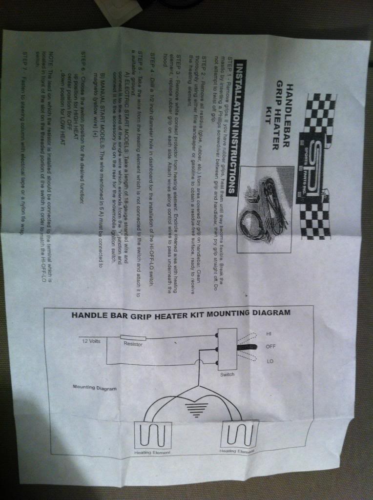
Thanks for the suggestions. I ordered Jeff's "kit" (from the ebay link). The components are the same as shown in the eBay picture, but I took a photo anyways, and also one of the instructions, below.
Unfortunately I am somewhat electrically-retarded. Wondering if I can get a step by step "guide" for installing this on a CBR600F4. According to the instructions I should ground the [free] wires from the heating elements. I need to a suitable ground? Also, there is no information on connecting this to the battery, I'm confused. Should I get a separate relay for this? I'd like for the engine to be on for it to turn on regardless of switch position. Sorry for my lack of experience here!
Many thanks for advice.
BBP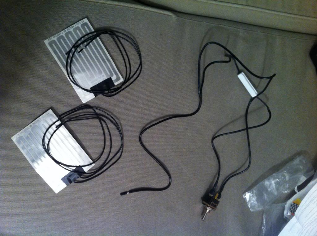
#13
12-28-2012, 11:19 AM

June 2013 ROTM
Well a suitable ground can be pretty much anywhere on your bike where a bolt sits into the frame metal. If you have a multimeter (which if you don't, go get one from canadian tire or somewhere, they are less than $20), set it to resistance (ohms, omega symbol) touch one test lead to the negative (black) terminal of your battery and touch the other to the bolt you want to use. If it reads 0 (or a low decimal value), you have found a good ground.
As for the 'positive' side, where the resistor sits, you will have to tap/splice an accessory line to get the key to override the switch position. I don't have an F4, so I can't be sure, but on my F1, there is a wire that is for "parking light". The canadian imports didn't come with any light installed, so I just used that for my LED kit. You don't connect it to the battery at all - that would mean the heaters would only be controlled by the switch, not the key. This way, the heaters are connected to the battery via the key.
EDIT: I found a F4i wiring diagram, which I am sure is fairly similar to the F4. There should be a Blue/Red wire that is the headlight power (before the relay). That should work.
Last edited by CorruptFile; 12-28-2012 at 11:28 AM.
#14
12-28-2012, 12:54 PM
June 2013 ROTM
After thinking about it, putting these directly on the light circuit might be too much draw. Probably best to use a simple relay.
$5 at CT
Pilot Automotive 40 Amp Relay | Canadian Tire
Here is a diagram
$5 at CT
Pilot Automotive 40 Amp Relay | Canadian Tire
Here is a diagram
#15
12-28-2012, 02:01 PM
After thinking about it, putting these directly on the light circuit might be too much draw. Probably best to use a simple relay.
$5 at CT
Pilot Automotive 40 Amp Relay | Canadian Tire
Here is a diagram
$5 at CT
Pilot Automotive 40 Amp Relay | Canadian Tire
Here is a diagram
BBP
EDIT: Also, anything else I should get at Canadian Tire for this to work? I may be able to go there later today.
Last edited by BlueBerryPie; 12-28-2012 at 02:21 PM.
#16
12-28-2012, 02:35 PM
June 2013 ROTM
There is a couple ways to do it. I presume you aren't very proficient at soldering (but now would be a great time to learn!). If you can solder, I would cut a powered source (looking at the wiring diagram - there is a black/brown wire coming from the "B" position on the fuse box) in half and twist-solder one of the ends together with your lead from the relay. If you don't want to solder, you can splice using a butt connector like this:

Not ideal, but it would work (I'd use some silicon sealant to seal the ends, then wrap it all well in electrical tape).
As for attaching to the relay itself, you can solder, or use female spade connectors, which you can crimp on.
Not ideal, but it would work (I'd use some silicon sealant to seal the ends, then wrap it all well in electrical tape).
As for attaching to the relay itself, you can solder, or use female spade connectors, which you can crimp on.
#17
12-28-2012, 02:55 PM
#18
12-28-2012, 08:23 PM
June 2013 ROTM
#19
12-29-2012, 12:40 AM
OK, will try this in next few weeks (bike in friends' for winter) and report results. Thanks for the tips/help!
#20
12-29-2012, 01:00 AM

Senior Member
Join Date: Oct 2011
Location: Monticello, Indiana
Posts: 777
Likes: 0
Received 0 Likes
on
0 Posts
i would personally do it the way corrupt has it in the diagram he posted, wouldnt have to worry about splicing another wire into the harness, just run a fused wire straight to the battery. that way you wouldnt have to worry about another circuit in the bike being overloaded and possibly popping a fuse.