
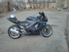
Crazytaxi's 1998 CBR 600 F3


Thread Starter
|
Member
Joined: Apr 2010
Posts: 36
Likes: 0
From: Norway
I Spliced them together with cable shoes to the original Wiring via the LED relay that was there from the old miniblinkers.
I had to remove a good deal of the insulation from the wire, because it's so thin that I had to twist the wire with itself to make it thick enough, so the cable shoe would sit firmly to the wire.. :P
It was just a matter of putting all the positive wires togheter, and the negative ones together. And use a healthy portion of black insulation tape so that they don't come apart.. hehe
Thread Starter
|
Member
Joined: Apr 2010
Posts: 36
Likes: 0
From: Norway
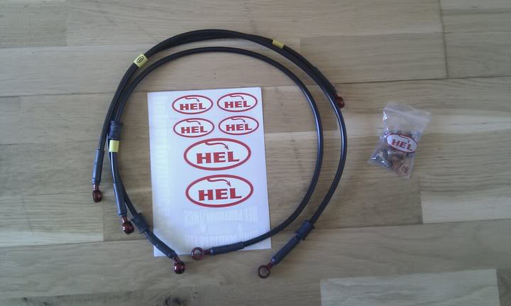
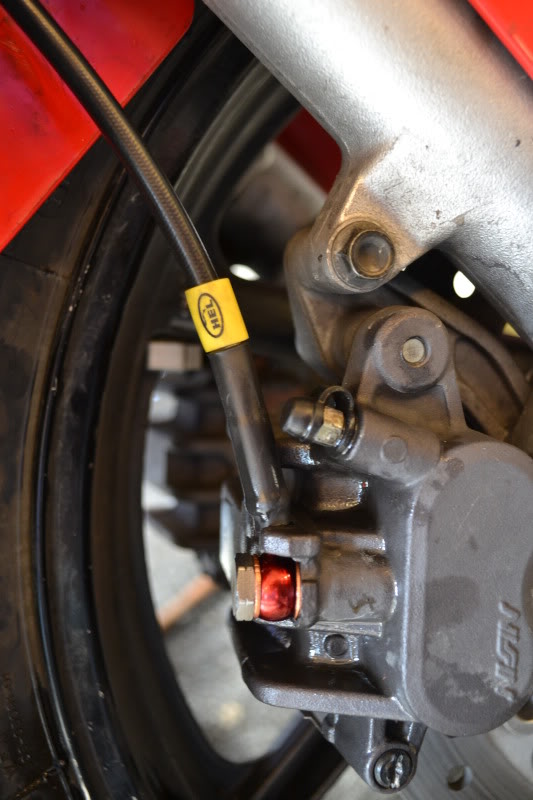
Bought some HEL braided brake Lines a while back, but due to a little vacation Riding Route 66 I haven't gotten around to installing them before now...
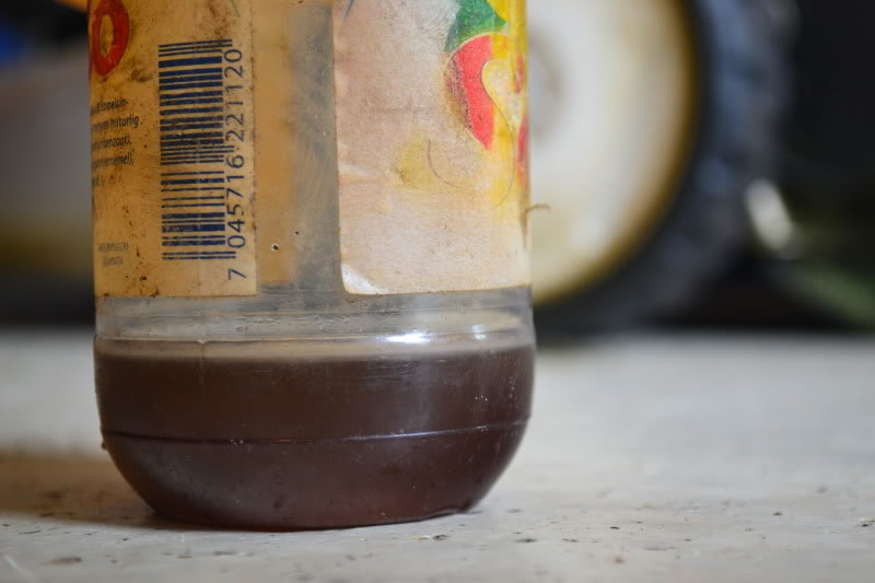
And this shows that is was way overdue to change the brake-fluid:
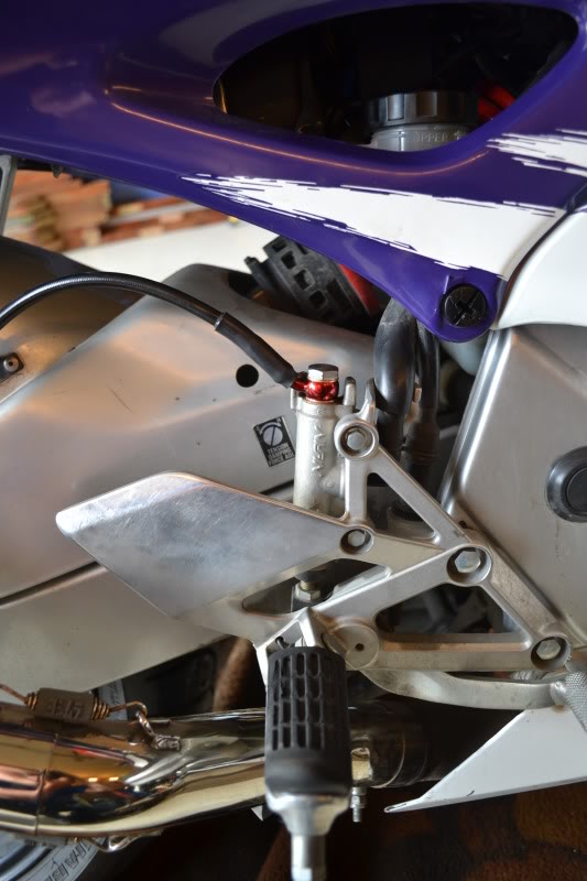
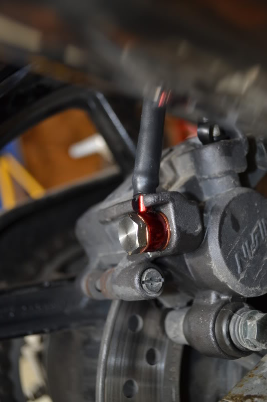
New Rear Brake-Line:
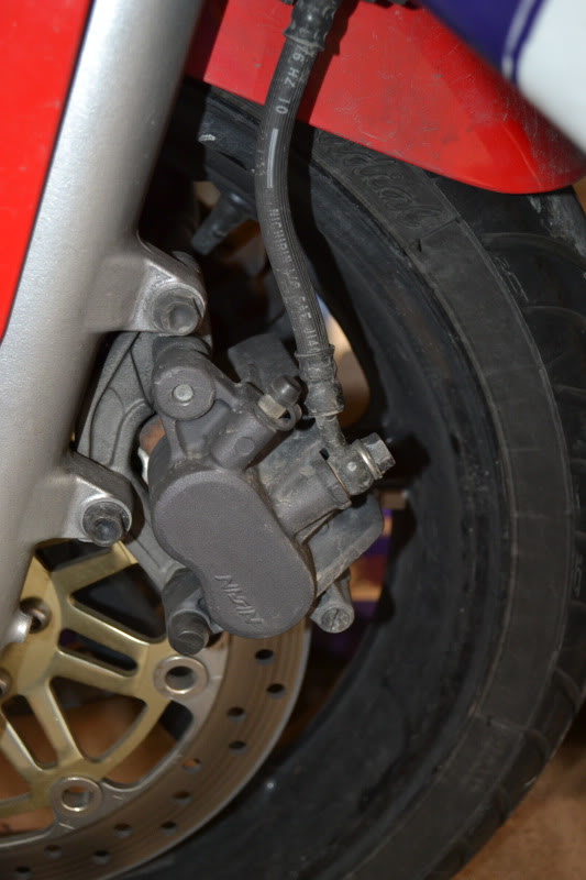
Old vs New Front Brake-Lines:
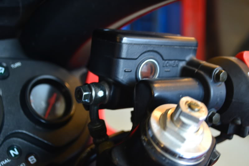
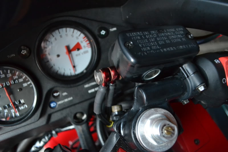
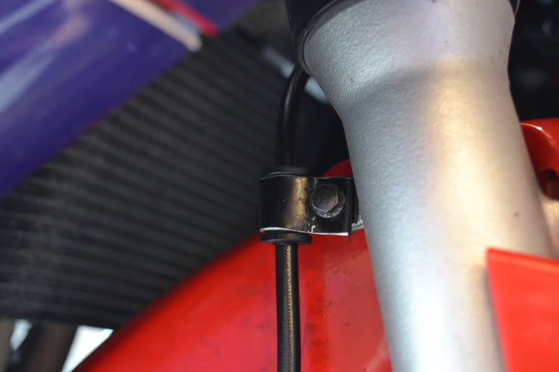
Since I bought the two-line setup, with two seperate Brakelines going to the front brakes, I needed to make new mounting points:
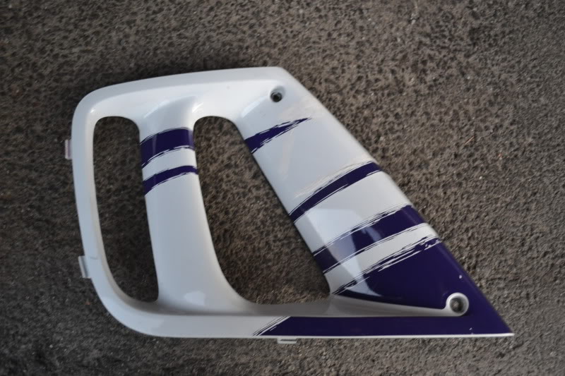
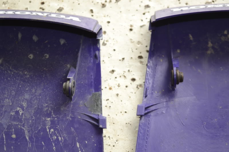
I also bought some new fairing parts:
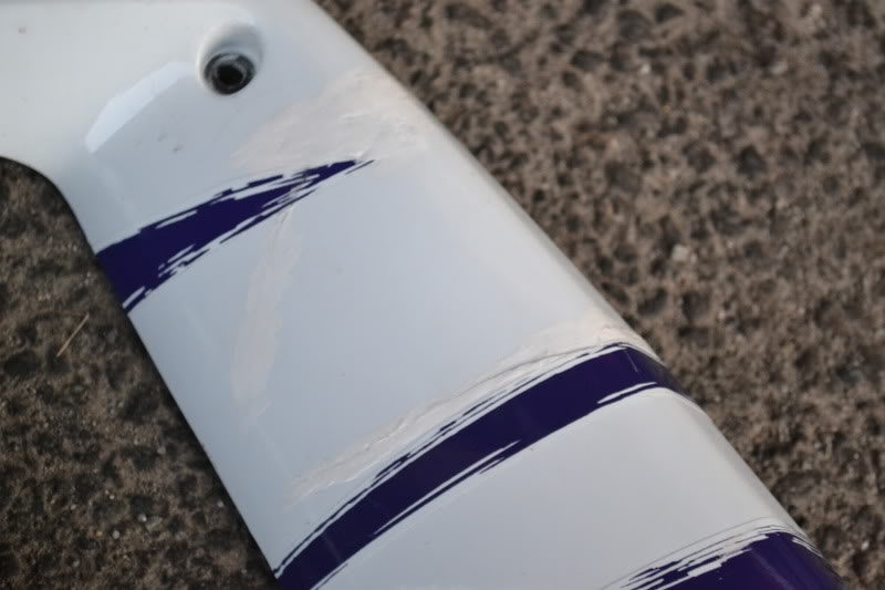
Old Side fairing insert, that previous owner tried to fix with White-Out or something:
New:
Old vs New Tail-Fairing:
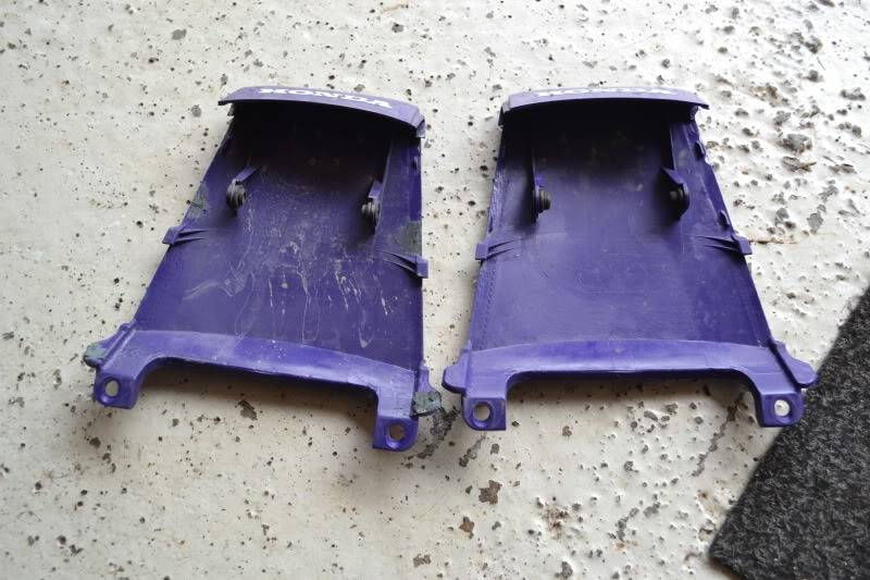
Old Tail-Fairing:
And this shows that is was way overdue to change the brake-fluid:
New Rear Brake-Line:
Old vs New Front Brake-Lines:
Since I bought the two-line setup, with two seperate Brakelines going to the front brakes, I needed to make new mounting points:
I also bought some new fairing parts:
Old Side fairing insert, that previous owner tried to fix with White-Out or something:
New:
Old vs New Tail-Fairing:
Old Tail-Fairing:
Thread Starter
|
Member
Joined: Apr 2010
Posts: 36
Likes: 0
From: Norway
Well time to bring this one back to life then..
I've just been riding the bike the last couple of years.. and the things that have been done, is just regular service, and fitted new tyres, Metzeler Roadtec Z8 front and rear.. And went from a 180 rear tyre fitted by the prevoius owner to the original 160.. It was a completly different bike to ride.. the turn in to corners was so much smoother and gives much better feedback..
The main reason for dragging this thread back to life, is that I'm in the process of converting to the f4i gauges..
I've gotten the schematics from the Service manual for the f4i Which has these colour codes
Temp (-)---G / Bu------Green / Blue
Speed------P / G-------Pink / Green
Ign (+)-----Bl / Br------Black / Brown
Illumi (+)---Br / W------Brown / White
Batt (+)----R / G-------Red / Green
Fi Ind (-)---W / Bu-----White / Blue
Tacho------Y / G-------Yellow / Green
Oil (-)------Bu / R------Blue / Red
Turn R(+)---Lb----------Light Blue
Hi Beam (+) -Bu---------Blue
Neutral (-)--Lg / R-------Light Green / Red
Turn L (+)---O----------Orange
(-)----------G----------Green
Sensor (-)---G / Bl------Green / Black
Res. Sens---Br / Bl-------Brown / Black
Side Stand--G / W------Green / White
F3:
Coolant Temp----------Green / Blue
Speed Sensor----------Pink / Green
Ign (+)-----------------Black / Brown
Illumi (+)---------------Brown
Batt (+)----------------Red / Green
Tacho-----------------Yellow / Green
Oil (-)------------------Blue / Red
Turn R(+)--------------Light Blue
Hi Beam (+)------------Blue
Neutral (-)-------------Light Green / Red
Turn L (+)-------------Orange
(-)--------------------Green
Sensor (-)-------------Green / Black
Side Stand-------------Yellow / Black
(-)--------------------Green
Speedo (-)------------Pink
Which gives me these Connections:
-----------------F4i--------------F3
Temp (-)----Green / Blue------Green / Blue
Speed-------Pink / Green------Pink / Green
Ign (+)------Black / Brown-----Black / Brown
Illumi (+)----Brown / White-----Brown
Batt (+)-----Red / Green-------Red / Green
Fi Ind (-)----White / Blue------Not Used (Side Stand Yellow / Black)
Tacho-------Yellow / Green----Yellow / Green
Oil (-)-------Blue / Red--------Blue / Red
Turn R(+)----Light Blue---------Light Blue
Hi Beam (+)--Blue --------------Blue
Neutral (-)---Light Green / Red--Light Green / Red
Turn L (+)---Orange-----------Orange
(-)----------Green-------------Green
Sensor (-)---Green / Black------Green / Black
Res. Sens----Brown / Black------Not Used
Side Stand---Green / White------Yellow / Black
This means that on the Wiring harness on the F3 there's one Pink and one Green wire, that's not used.
I've read that the pink one should be grounded to the chassis.
The Other Green should just be left unused.
And that the Batt (+) Red / Green should use an 10 a fuse.
Some pictures to follow :P
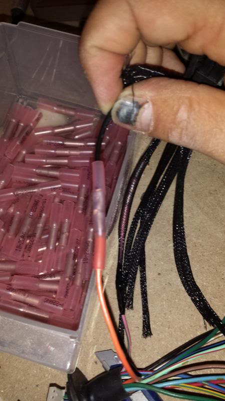
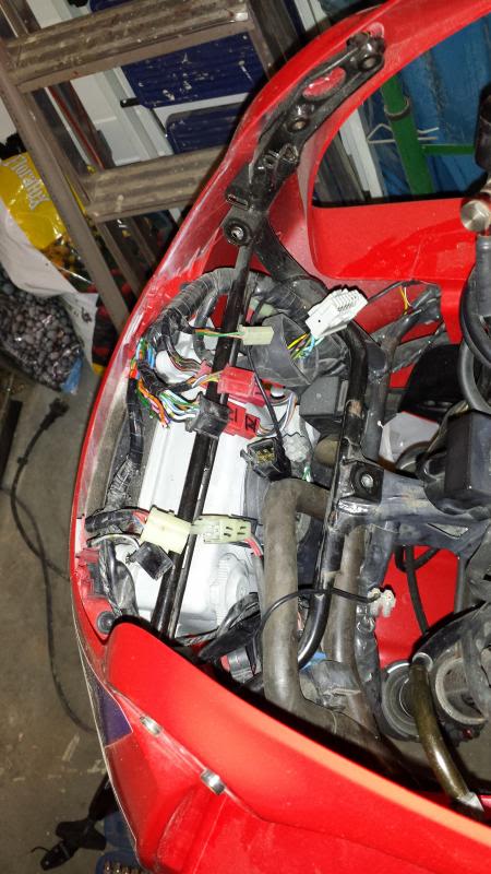
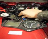
Connecting the new cables from the f4i to a 8-pin PCIe power cable, using marine grade connectors that you melt with a heating gun:
I wanted to reuse an orginal housing, to keep the look as OEM as possible, so i used my router to make som templates in mdf, before making the insert inn 6,5mm plexi:
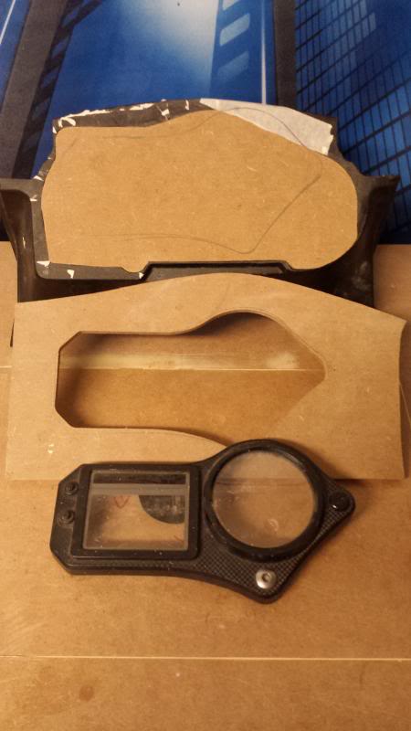
Just put it in, to se approx what it will look like. The Plexi will be painted black, to match the rest of the housing, and nothing is glued together in that picture, everything is just pushed together.
How it looked when I called it a night yesterday:
I've just been riding the bike the last couple of years.. and the things that have been done, is just regular service, and fitted new tyres, Metzeler Roadtec Z8 front and rear.. And went from a 180 rear tyre fitted by the prevoius owner to the original 160.. It was a completly different bike to ride.. the turn in to corners was so much smoother and gives much better feedback..
The main reason for dragging this thread back to life, is that I'm in the process of converting to the f4i gauges..
I've gotten the schematics from the Service manual for the f4i Which has these colour codes
Temp (-)---G / Bu------Green / Blue
Speed------P / G-------Pink / Green
Ign (+)-----Bl / Br------Black / Brown
Illumi (+)---Br / W------Brown / White
Batt (+)----R / G-------Red / Green
Fi Ind (-)---W / Bu-----White / Blue
Tacho------Y / G-------Yellow / Green
Oil (-)------Bu / R------Blue / Red
Turn R(+)---Lb----------Light Blue
Hi Beam (+) -Bu---------Blue
Neutral (-)--Lg / R-------Light Green / Red
Turn L (+)---O----------Orange
(-)----------G----------Green
Sensor (-)---G / Bl------Green / Black
Res. Sens---Br / Bl-------Brown / Black
Side Stand--G / W------Green / White
F3:
Coolant Temp----------Green / Blue
Speed Sensor----------Pink / Green
Ign (+)-----------------Black / Brown
Illumi (+)---------------Brown
Batt (+)----------------Red / Green
Tacho-----------------Yellow / Green
Oil (-)------------------Blue / Red
Turn R(+)--------------Light Blue
Hi Beam (+)------------Blue
Neutral (-)-------------Light Green / Red
Turn L (+)-------------Orange
(-)--------------------Green
Sensor (-)-------------Green / Black
Side Stand-------------Yellow / Black
(-)--------------------Green
Speedo (-)------------Pink
Which gives me these Connections:
-----------------F4i--------------F3
Temp (-)----Green / Blue------Green / Blue
Speed-------Pink / Green------Pink / Green
Ign (+)------Black / Brown-----Black / Brown
Illumi (+)----Brown / White-----Brown
Batt (+)-----Red / Green-------Red / Green
Fi Ind (-)----White / Blue------Not Used (Side Stand Yellow / Black)
Tacho-------Yellow / Green----Yellow / Green
Oil (-)-------Blue / Red--------Blue / Red
Turn R(+)----Light Blue---------Light Blue
Hi Beam (+)--Blue --------------Blue
Neutral (-)---Light Green / Red--Light Green / Red
Turn L (+)---Orange-----------Orange
(-)----------Green-------------Green
Sensor (-)---Green / Black------Green / Black
Res. Sens----Brown / Black------Not Used
Side Stand---Green / White------Yellow / Black
This means that on the Wiring harness on the F3 there's one Pink and one Green wire, that's not used.
I've read that the pink one should be grounded to the chassis.
The Other Green should just be left unused.
And that the Batt (+) Red / Green should use an 10 a fuse.
Some pictures to follow :P
Connecting the new cables from the f4i to a 8-pin PCIe power cable, using marine grade connectors that you melt with a heating gun:

I wanted to reuse an orginal housing, to keep the look as OEM as possible, so i used my router to make som templates in mdf, before making the insert inn 6,5mm plexi:


Just put it in, to se approx what it will look like. The Plexi will be painted black, to match the rest of the housing, and nothing is glued together in that picture, everything is just pushed together.

How it looked when I called it a night yesterday:

Last edited by crazytaxi; Oct 3, 2013 at 04:40 AM.

Thread Starter
|
Member
Joined: Apr 2010
Posts: 36
Likes: 0
From: Norway
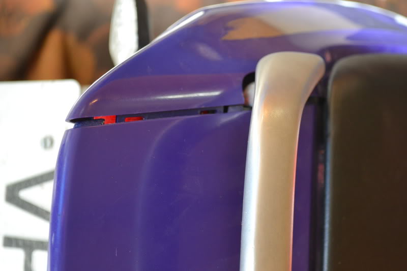
Starting to see the end of the gauge swap now.
Reused the second part of the housing, to get the mounting tabs, angle and height as close to oem as possible:
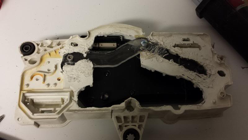
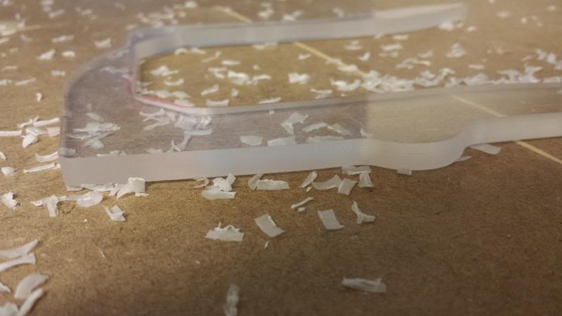
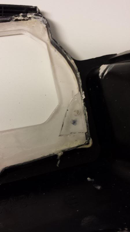
Used 6,5mm plexi that I plastic-welded to the housing to mount the f4i gauges.
when I cut out the front of the old housing, I also cut away some of the mounting points for the back piece, so I had to fabricate some mounting points:
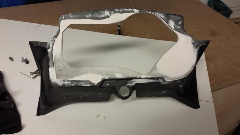
Ready for paint:
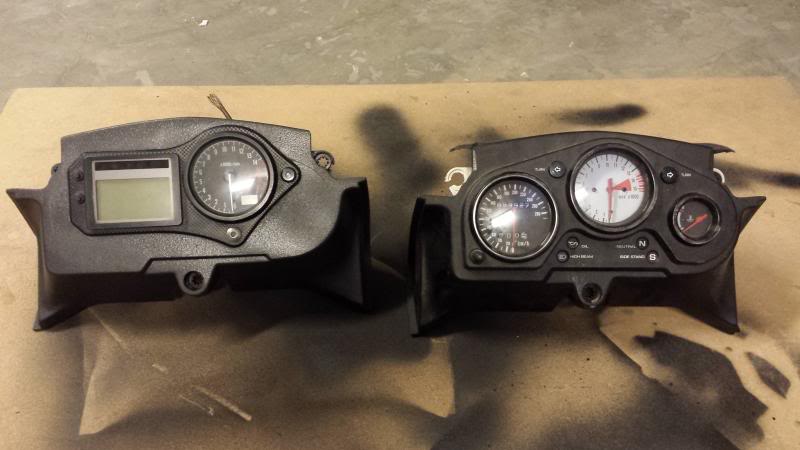
New vs Old:
Reused the second part of the housing, to get the mounting tabs, angle and height as close to oem as possible:

Used 6,5mm plexi that I plastic-welded to the housing to mount the f4i gauges.
when I cut out the front of the old housing, I also cut away some of the mounting points for the back piece, so I had to fabricate some mounting points:

Ready for paint:

New vs Old:

Thread Starter
|
Member
Joined: Apr 2010
Posts: 36
Likes: 0
From: Norway
Thanks guys 
I've also added a K&N filter and replaced the windscreen with a Zero Gravity one. ( I had a cheap double bubble screen before, but it looked just wrong )
)
Because the bike is 15 years old, and had a hard life before it came to me it seems.. I'm constantly on the lookout on ebay for bits and pieces to make it better looking.
I've also added a K&N filter and replaced the windscreen with a Zero Gravity one. ( I had a cheap double bubble screen before, but it looked just wrong
)Because the bike is 15 years old, and had a hard life before it came to me it seems.. I'm constantly on the lookout on ebay for bits and pieces to make it better looking.
Thread Starter
|
Member
Joined: Apr 2010
Posts: 36
Likes: 0
From: Norway
Finished Putting the bike together again tonight..
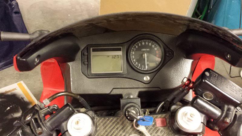
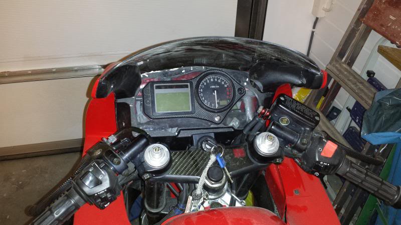
With ign on:
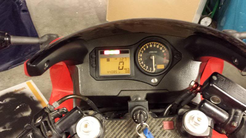
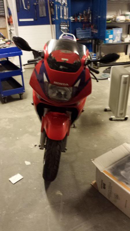
And one shot from the front to show the Zero Gravity Light tinted windscreen:
Does anybody know how much work it is to change the lighting in these gauges.. was wondering about using red maybe..

With ign on:

And one shot from the front to show the Zero Gravity Light tinted windscreen:

Does anybody know how much work it is to change the lighting in these gauges.. was wondering about using red maybe..