
1000F-L balancer shaft photos

As my engine is in bits at the moment.
I thought you guys might like to see what's hidden inside.
Here's some photos of the balancer shaft and it's various components as I found them during disassembly.
I'll put some other photos up here when I've got time. I'm sure there'll be plenty of people interested in seeing the inside of this engine. Food for thought if you have a problem. If you've any specific requirements for pics let me know and I'll be happy to oblige.
The shaft that holds this assembly into the engine case is not shown. I forgot to line it up for the pictures.
I'll describe what you're seeing in these.
One thing that surprised me is the fact that the cog that drives the balancer is made of plastic. It doesn't tell you that in the manual or parts catalogue! Makes sense though and perhaps explains why, if over tightened against the crank gear it makes a high pitched whine. Many epople on the forum have described hearing that. The bearing shaft is actually an eccentic cam which can be adjust externally. See your manual for more info on that or visit the numerous links in the forum.
I'm going to replace the cush drive rubbers. They're like... rock hard and have shrunk causing rotational play between the gear and the shaft. Not what you need.
Here you go.... fill ya boots.....

This is the balancer assembly (minus central shaft)

These are the needle bearing cages and spacer that holds them apart which separate the balancer and shaft. I couldn't detect any play in the assembly. Good for another 60K I'd say. The end caps hold the cages away from the crank case. It fits in there very nicely and is a nicely machined clearance fit overall.

The balancer close up. Note the black plastic cog. it seems in good condition with no obvious signs of wear or cracking.

Starting to remove the metal balancer from the plastic cog

Here it comes....

It comes apart without any fight at all. Note the splines on the metal shaft which fit between the cush drive rubbers

You can see that the rubber pads are fitted both sides of the splines. This gives a damping effect in both rotaional directions, accelerating and decelerating.

Now you can see the rubber clearly. These are knackered. Can't wait to feel the difference when the new ones go in.
By the way, this operation can be carried out through the sump.
To remove the balancer you undo the external clamp bolt, undo a 6mm bolt within the sump enclosure and Bob's your uncle, it just drops out when you withdraw the central shaft.
Honda don't seem to give an indication in their manuals about how often these should be replaced but I'd say its probably worth while doing as often as you do a cam chain and certainly much easier.
A set of rubbers and a sump gasket is about �20.00. Not big beans. Don't forget to replace the o ring at the end of the central shaft which keeps it sealed from the elements.
I'll let you know how the new rubbers look and affect the assembly when I rebuild the thing in the coming weeks.
I thought you guys might like to see what's hidden inside.
Here's some photos of the balancer shaft and it's various components as I found them during disassembly.
I'll put some other photos up here when I've got time. I'm sure there'll be plenty of people interested in seeing the inside of this engine. Food for thought if you have a problem. If you've any specific requirements for pics let me know and I'll be happy to oblige.
The shaft that holds this assembly into the engine case is not shown. I forgot to line it up for the pictures.
I'll describe what you're seeing in these.
One thing that surprised me is the fact that the cog that drives the balancer is made of plastic. It doesn't tell you that in the manual or parts catalogue! Makes sense though and perhaps explains why, if over tightened against the crank gear it makes a high pitched whine. Many epople on the forum have described hearing that. The bearing shaft is actually an eccentic cam which can be adjust externally. See your manual for more info on that or visit the numerous links in the forum.
I'm going to replace the cush drive rubbers. They're like... rock hard and have shrunk causing rotational play between the gear and the shaft. Not what you need.
Here you go.... fill ya boots.....
This is the balancer assembly (minus central shaft)
These are the needle bearing cages and spacer that holds them apart which separate the balancer and shaft. I couldn't detect any play in the assembly. Good for another 60K I'd say. The end caps hold the cages away from the crank case. It fits in there very nicely and is a nicely machined clearance fit overall.
The balancer close up. Note the black plastic cog. it seems in good condition with no obvious signs of wear or cracking.
Starting to remove the metal balancer from the plastic cog
Here it comes....
It comes apart without any fight at all. Note the splines on the metal shaft which fit between the cush drive rubbers
You can see that the rubber pads are fitted both sides of the splines. This gives a damping effect in both rotaional directions, accelerating and decelerating.
Now you can see the rubber clearly. These are knackered. Can't wait to feel the difference when the new ones go in.
By the way, this operation can be carried out through the sump.
To remove the balancer you undo the external clamp bolt, undo a 6mm bolt within the sump enclosure and Bob's your uncle, it just drops out when you withdraw the central shaft.
Honda don't seem to give an indication in their manuals about how often these should be replaced but I'd say its probably worth while doing as often as you do a cam chain and certainly much easier.
A set of rubbers and a sump gasket is about �20.00. Not big beans. Don't forget to replace the o ring at the end of the central shaft which keeps it sealed from the elements.
I'll let you know how the new rubbers look and affect the assembly when I rebuild the thing in the coming weeks.

There have been quite a few posts on here about the rubbers but only one person I can remember has ever done the job. There was about 1mm of twisting play between the shaft and the cog. Not a spec Honda tolerance I'm sure. Interesting to see it in the flesh though aint it?


Here ya go. I've got loads of pics to help me remember how it all goes back together as much as anything else. Any other requests?

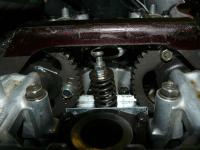
Here you can see all the oil plumbing and at the top left is the balancer shaft. The black bolt head is the one which holds the balance shaft in place. The bolt is a special which has a round tip and locates into a groove in the shaft to allow it to turn for adjustment. If you needed to get the balancer out for changing the rubbers or renewing you'd just have to remove the oil feed pipe.
The chain draped over the oil pump is the cam chain as I'd already removed the cams by this stage.
The oil pump has no tensioner by the way and although I'm going to renew the chain I think the guide is in good nick but I'm going to change it anyway. I'll put a micrometer on the old and new to check for wear and include that data in the final report.
A quick update. I think I need my eyes overhauled. The cog is not plastic. It's definitely steel. Very hard steel, possibly coated with something or possibly polished. I was just looking for the marks that are supposed to be lined up and dropped it. No damage but the 'ring' made me think, "that's not plastic" (is it grammatically correct to use speech marks for something that thought?). Sorry for the misinformation. Metal.... metal cog OK!
Here's a couple of pages from the manual to clear things up and help you see what you're looking at in the last picture.


Beer time!
Here's a couple of pages from the manual to clear things up and help you see what you're looking at in the last picture.
Beer time!