Valve Adjustment Guide
#1
 10-08-2009, 10:23 AM


Join Date: Apr 2009
Location: Arlington, TX
Posts: 147
Likes: 0
Received 0 Likes
on
0 Posts
I found this on Musclecross.com posted by a guy named Mike. Great guy considering all the work he put into writing this! He said it was cool if I post it up here. Thanks!!
Valve Adjustment Guide- CBR 600 F2/F3
Over time, the valves on your F2/F3 are going to go out of adjustment. The interval to check is usually about 11,000 miles. While this can be performed at home, there are some challenges to be aware of before you begin.
Engine Overview:
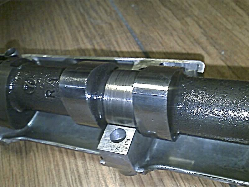
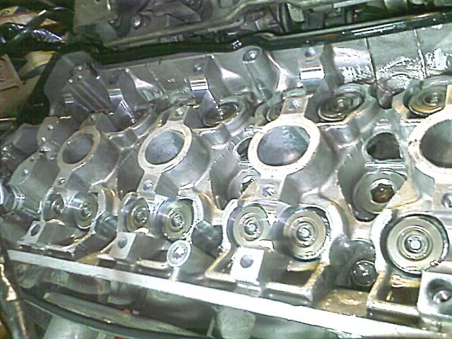
Let's begin with a brief overview of the vavletrains design. The F2/F3 is a dual overhead cam, 16 vavle 4 cylinder engine. That means each cylinder has 4 valves (two intake vavles located under the intake cam and two exhaust valves located under the exhaust cam). The lobes of the cam rotate directly against the end of the valves caps, which shroud the valve spring. Between the valve cap and the valve spring are the valve shims. These are available in various thickness as the means to get the correct valve lash (desired adjustment) between the valve and the lobe of the cam. The shim design is very small, light, simple, reliable and effective. This wastes little power to actuate the valve.
Valvetrain Design Considerations:
The reason lash is important is due to an engines heat cycle. As metal heats up, it expands. If there were no gap then the expanding metal would start holding the valves open all the time and you would loose compression/power. Have too much of a gap and the valvetrain will be noisy, not open all the way and loose power. You might ask yourself, how come they do not automaticlly adjust... this to is possible. Passenger cars often run hydraulic lifters which use a little bit of power to adjust the vavle while the engine is operating, at the expense of making the valvetrain heavier.
Gotchas for the Home Mechanic:
The first gotcha is in the design. Many shops and dealers will not have the shims you need in stock. This would require dissasembling the bike and valvetrain to take measurements, ordering the shims, reassemble the bike, wait for the shims, disassembe again and finally install the new shims. Or you can leave the bike apart while you wait. Don't get discouraged if that poses a problem, you can sometimes get lucky and simply rearrange your existing shims to do the whole job. It at least will reduce the cost of new shims if you can reuse some. See the case study at the end of this article for a real world use case of how it is done.
Tools Needed:
Ratcheting Socket set
10mm socket.
14mm socket
Metric Feeler Guage
Micrometer (digital is best)
Good strong small magnet
Let's Begin:
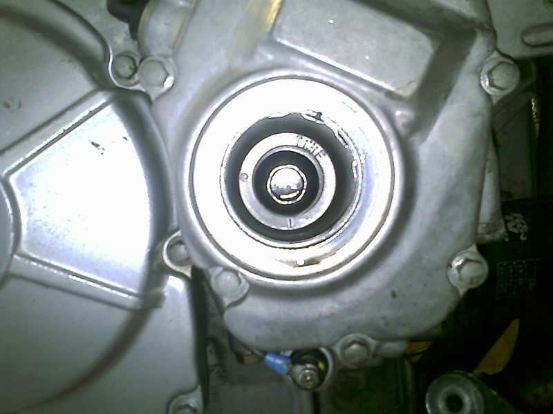
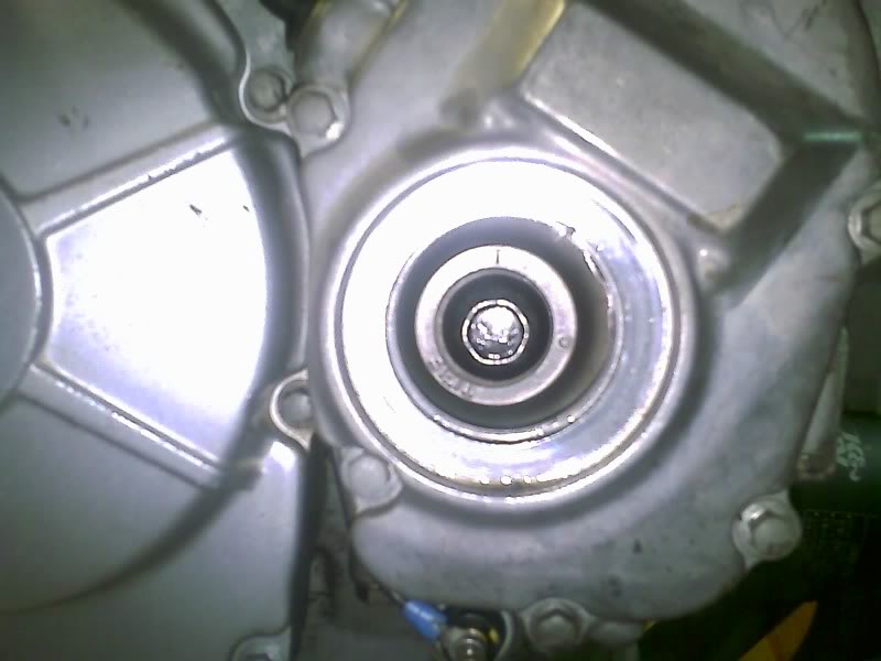
This can all be done with the bike on the kickstand. You will first need to get to the valve cover. On the F2/F3, this means removing the tank, the airbox from the carbs and the coils. Make sure to mark the plugwires, coils and wires to each plug on the coils before removing them. This is so that assembling them later is very easy and fast. You will need to unbolt the radiator from the frame but you do not need to drain it. Simply allow it to hang down out of the way. If you have an F3, then also remove the ram-air below the neck. You should now be able to remove the 6 10mm bolts on the valve cover and lift the cover off. On the right side of the engine, remove the circular timing cover by its 17mm formed in head. This will give you visual access to the timing marks.
Measuring:
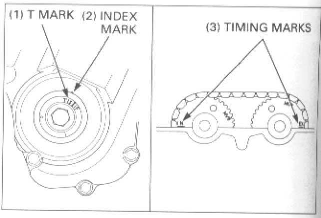
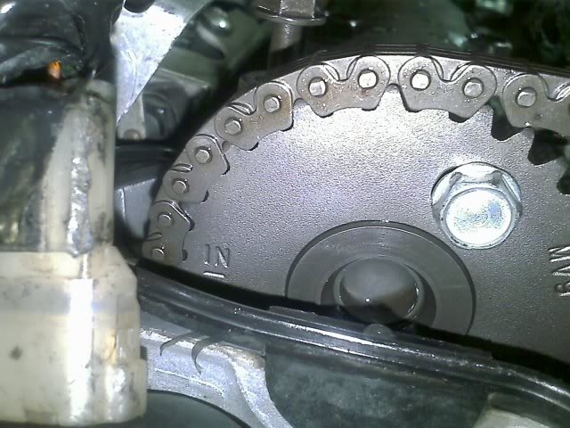
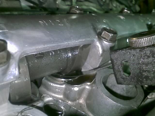
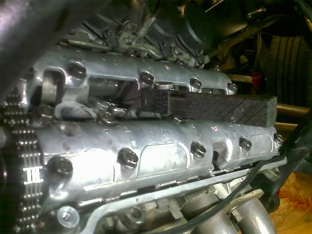
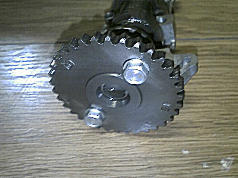
Before you can measure, you must get the engine at top dead center for the #1 and #3 cylinders. Each cam gear is marked as "IN" for intake and "EX" for exhaust. Turn the engine over using the 14mm bolt exposed under the timing cover, rotating clockwise (tightening). Align the "Tl" on the pulse rotor with a line "l" on the outer cover at the 2 o'clock position. When the "IN" on the left side of the left cam gear is lined up with the surface of the top of the head, and the "EX" is also lined up but on the right cam gear on the far right side of the head and the "Tl" is lined up at the pulser cover then you are ready to begin.

Get a piece of paper and draw two rows of 8 circles on it to represent each vavle on the bike. Since you will be working mostly from the front of the bike, mark the top row intake and the bottom row exhaust. Now number the circles left to right on each row, starting with 4a, 4b, 3a, 3b, 2a, 2b, 1a, 1b to represent each vavlue uniquely.
Now measure the #1 and #3 cylinders intake valves with your gap tool by inserting a .16mm shim under between each cam lobe and vavle spring cap. Remember, the numbers of the intake vavles when looking at the valves from the front of the bike is the same as on the paper. If the .16 wont fit, then try a smaller one. If its too loose then try a bigger one. Document your gaps above each of the related circles on your paper.
Now turn the timing mark 180 degrees clockwise so that it is opposite the case mark. Now measure the exhaust #2 and #4 and document those results.
Now turn the timing mark clockwise 180 degrees to the timing mark. Note the cams are not lines up as In and EX. We are 360 degrees off of #1 top dead center which allows us to now measure the #2 and #4 intake. Write down your results.
Now turn the timing mark 180 degrees to be once again opposite the case mark. Measure #1 and #3 exhaust valves and write this down. Turn the timing mark clockwise 180 degrees to where the timing mark matches the case mark, and the IN and EX marks on the cam gears line up with the top of the head. You are back to the begginning.
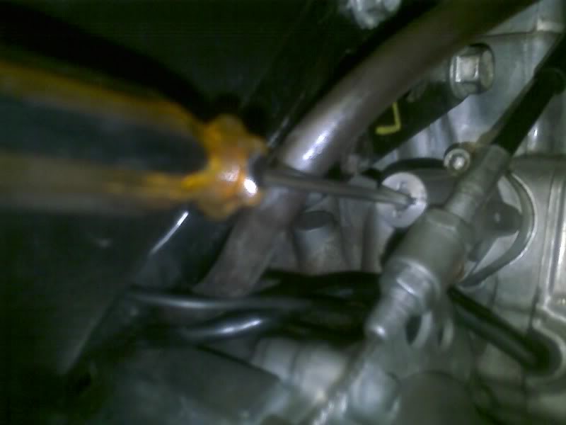
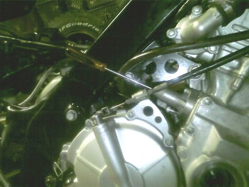
Once this is complete, it is time to pull the cams retianers out one at a time. Start by loosening the cam chain tensioner on the right rear of the engine. To do this, removethe single bolt at the tip of the unti. This exposes a hole down to a small flathead which is sprung to stay exteanded. By twisting the flathead you can unload the spring which allows the tensioner to release internally. Loosen this all the way and brace the screwdriver to the frame. This should hold it sprung open while you work as well as relieve tension on the cam chain.
While I removed both cams, you can do just one cam at a time and let the other cam hold the chain up. It goes much quicker this way. For the sake of the write up though, I removed both for clarity. Remember, the cam gears say IN and EX so you cant mix them up. Now remove the exhaust cam retaining bolts careful not to drop them in the engine. Once removed, lift the cam up opposite the cam gear to allow a little slack in the chain. Unhook the chain from the cam gear and remove the cam. Take a moment to look the cam lobes and bearing surfaces for signs of wear. They should be smooth and free of any discoloration or grooves. Aslo check the teeth on the cam gear for wear.
Remove the intake cam in the same manner and set it aside. If you remove both cams, then zip tie the cam chain to a cable or anything above the head to keep it from falling in.
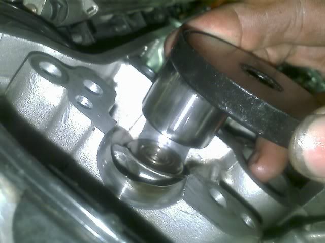
Using the magnet, remove each spring cap and place it somewhere that you can keep the orientation of which valve it came off of. I lined mine up below the engine on the floor for now- but later moved them to a marked box the kept them oriented correctly.
You do not want to mix these up so make sure you can remember which one came off of which valve - or else you will have to start over. Now carefully remove the shim from the underside of each retainer (it make have remained on the valve).
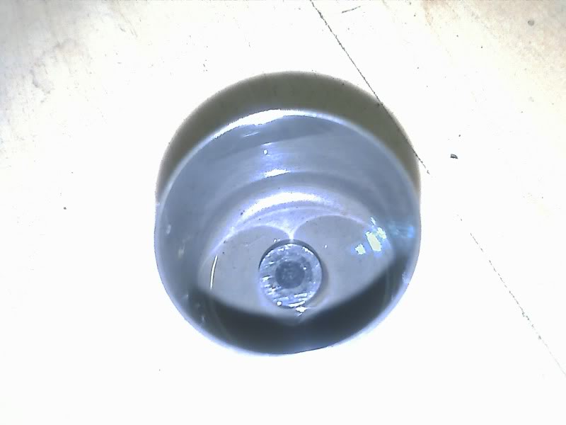
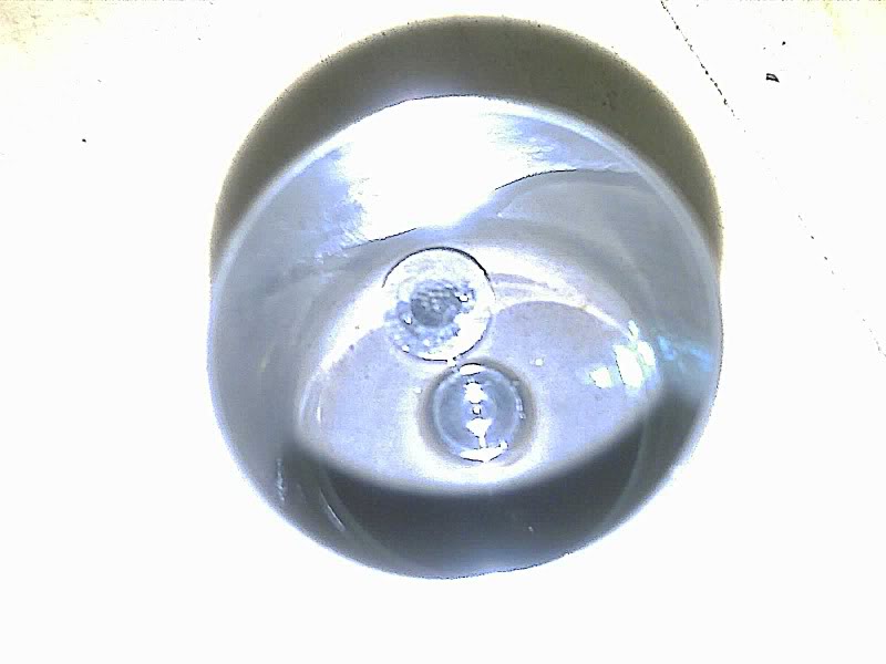
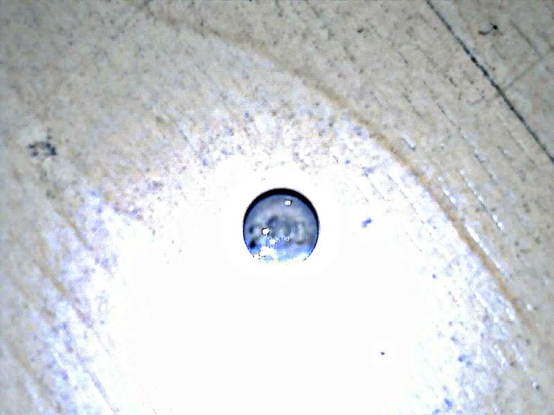
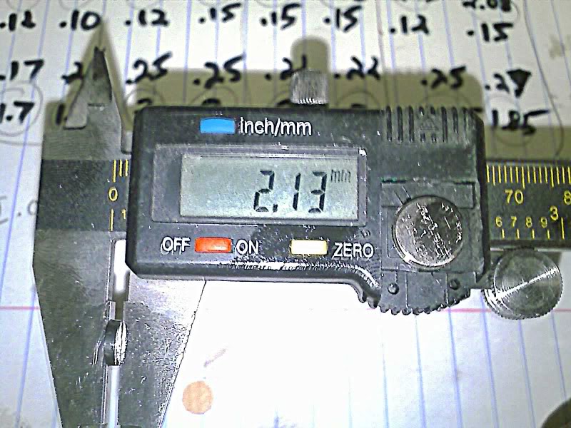
These have numbers on them but wear and tear usually rubs them off. If you can see the number, great. If not, then measure its thickness with the micrometer and document it on your gap sheet in the middle of each respective circle.
Now that you have all these measurements, its time to make sense of them. What we need to do is figure out which shims need to be changed and which ones can be reused. this way, we know what to order.
Below is a Case Study of my 97 CBR 600 F3 as a direct example of how the above is applied. Here are my initial measurements:
Target Gap: 0.16mm +/- 0.03mm (0.006 in +/- 0.001 in)
Intake#: 4a 4b 3a 2b 2a 2b 1a 1b
Gap: .12 .10 .12 .15 .15 .15 .12 .15
Shim: 2.10 2.21 2.15 2.13 2.08 2.08 2.13 2.08
The measurements above show 4b to be too tight and a few others to be on the tighter side. In order to make it as close to perfect as possible. I would have to reshim it as shown below. Keep in mind that plus or minus 0.03mm is acceptable so a value of .13 to .19 is considered good. That being the case, this is how I configured mine:
Intake#: 4a 4b 3a 2b 2a 2b 1a 1b
ReGap: .16 .16 .17 .15 .15 .15 .16 .15
Reshim: 2.13 2.15 2.10 2.13 2.08 2.08 2.09 2.08
I used 1a's 2.13 and put it in 4a, 4a's 2.10 from 3a, 3a's 2.15 from 4b. That mixing corrected all but one, and leaves me buying a single 2.09 shim to use in 1a. That completes the intake. A 2.21 shim remains and is unused. See how that worked?
Next is the Exhaust:
Target Gap: 0.22mm +/- 0.03mm (0.009 in +/- 0.001 in)
Exhaust#: 4a 4b 3a 3b 2a 2b 1a 1b
Gap: .17 .22 .25 .25 .22 .22 .25 .27
Shim: 1.7 1.85 2 2 2 2 1.85 1.85
As you can see above, 4a is way too tight, and 1b is too loose. A few others are slightly off as well. This is not uncommon as F3 exhaust valves are known to wear faster. As the valve wears, it sinks into the head. It's stem gets closer to the cam and the lash decreases.
So lets do the same thing as the intake.
Exhaust#: 4a 4b 3a 3b 2a 2b 1a 1b
ReGap: .22 .22 .23 .23 .22 .22 .22 .22
Reshim: 1.65 1.85 2.02 2.02 2 2 1.88 1.90
It looks like I'm going to need to order a few here as well, since nothing crosses over.
Since I needed about 6 shims, and they are $8-$12 each depending on where you go (I went to a Yamaha Dealer as they use the same size and seem better stocked), it made sense to spend the $80 on a complete shim kit. This comes with 60 or so shims of all sizes in .05mm increments. This turned out to be the smarter thing as measuring the new shims showed they did not actualy measure as marked. By measuring the true width, I was able to get all my valves within +/- .01mm. Much better than originaly expected.
After swapping in the shims, replace the cam being carefull to realign the marks at Top Dead Center (TDC). Now run through the motions of checking all your intake gaps again. If you made a miscalculation, you will find it now. If you did it right, all your measurements should be within tolerance. If not, recalculate based upon the new measurements, remove the cam and just work on those that were off.
After everything was completed and the bike reassembled, it ran smooth as silk. A job well done and a good $500 remains in my pocket for doing it myself!
Take your time, and measure everything twice.
Valve Adjustment Guide- CBR 600 F2/F3
Over time, the valves on your F2/F3 are going to go out of adjustment. The interval to check is usually about 11,000 miles. While this can be performed at home, there are some challenges to be aware of before you begin.
Engine Overview:
Let's begin with a brief overview of the vavletrains design. The F2/F3 is a dual overhead cam, 16 vavle 4 cylinder engine. That means each cylinder has 4 valves (two intake vavles located under the intake cam and two exhaust valves located under the exhaust cam). The lobes of the cam rotate directly against the end of the valves caps, which shroud the valve spring. Between the valve cap and the valve spring are the valve shims. These are available in various thickness as the means to get the correct valve lash (desired adjustment) between the valve and the lobe of the cam. The shim design is very small, light, simple, reliable and effective. This wastes little power to actuate the valve.
Valvetrain Design Considerations:
The reason lash is important is due to an engines heat cycle. As metal heats up, it expands. If there were no gap then the expanding metal would start holding the valves open all the time and you would loose compression/power. Have too much of a gap and the valvetrain will be noisy, not open all the way and loose power. You might ask yourself, how come they do not automaticlly adjust... this to is possible. Passenger cars often run hydraulic lifters which use a little bit of power to adjust the vavle while the engine is operating, at the expense of making the valvetrain heavier.
Gotchas for the Home Mechanic:
The first gotcha is in the design. Many shops and dealers will not have the shims you need in stock. This would require dissasembling the bike and valvetrain to take measurements, ordering the shims, reassemble the bike, wait for the shims, disassembe again and finally install the new shims. Or you can leave the bike apart while you wait. Don't get discouraged if that poses a problem, you can sometimes get lucky and simply rearrange your existing shims to do the whole job. It at least will reduce the cost of new shims if you can reuse some. See the case study at the end of this article for a real world use case of how it is done.
Tools Needed:
Ratcheting Socket set
10mm socket.
14mm socket
Metric Feeler Guage
Micrometer (digital is best)
Good strong small magnet
Let's Begin:
This can all be done with the bike on the kickstand. You will first need to get to the valve cover. On the F2/F3, this means removing the tank, the airbox from the carbs and the coils. Make sure to mark the plugwires, coils and wires to each plug on the coils before removing them. This is so that assembling them later is very easy and fast. You will need to unbolt the radiator from the frame but you do not need to drain it. Simply allow it to hang down out of the way. If you have an F3, then also remove the ram-air below the neck. You should now be able to remove the 6 10mm bolts on the valve cover and lift the cover off. On the right side of the engine, remove the circular timing cover by its 17mm formed in head. This will give you visual access to the timing marks.
Measuring:
Before you can measure, you must get the engine at top dead center for the #1 and #3 cylinders. Each cam gear is marked as "IN" for intake and "EX" for exhaust. Turn the engine over using the 14mm bolt exposed under the timing cover, rotating clockwise (tightening). Align the "Tl" on the pulse rotor with a line "l" on the outer cover at the 2 o'clock position. When the "IN" on the left side of the left cam gear is lined up with the surface of the top of the head, and the "EX" is also lined up but on the right cam gear on the far right side of the head and the "Tl" is lined up at the pulser cover then you are ready to begin.
Get a piece of paper and draw two rows of 8 circles on it to represent each vavle on the bike. Since you will be working mostly from the front of the bike, mark the top row intake and the bottom row exhaust. Now number the circles left to right on each row, starting with 4a, 4b, 3a, 3b, 2a, 2b, 1a, 1b to represent each vavlue uniquely.
Now measure the #1 and #3 cylinders intake valves with your gap tool by inserting a .16mm shim under between each cam lobe and vavle spring cap. Remember, the numbers of the intake vavles when looking at the valves from the front of the bike is the same as on the paper. If the .16 wont fit, then try a smaller one. If its too loose then try a bigger one. Document your gaps above each of the related circles on your paper.
Now turn the timing mark 180 degrees clockwise so that it is opposite the case mark. Now measure the exhaust #2 and #4 and document those results.
Now turn the timing mark clockwise 180 degrees to the timing mark. Note the cams are not lines up as In and EX. We are 360 degrees off of #1 top dead center which allows us to now measure the #2 and #4 intake. Write down your results.
Now turn the timing mark 180 degrees to be once again opposite the case mark. Measure #1 and #3 exhaust valves and write this down. Turn the timing mark clockwise 180 degrees to where the timing mark matches the case mark, and the IN and EX marks on the cam gears line up with the top of the head. You are back to the begginning.
Once this is complete, it is time to pull the cams retianers out one at a time. Start by loosening the cam chain tensioner on the right rear of the engine. To do this, removethe single bolt at the tip of the unti. This exposes a hole down to a small flathead which is sprung to stay exteanded. By twisting the flathead you can unload the spring which allows the tensioner to release internally. Loosen this all the way and brace the screwdriver to the frame. This should hold it sprung open while you work as well as relieve tension on the cam chain.
While I removed both cams, you can do just one cam at a time and let the other cam hold the chain up. It goes much quicker this way. For the sake of the write up though, I removed both for clarity. Remember, the cam gears say IN and EX so you cant mix them up. Now remove the exhaust cam retaining bolts careful not to drop them in the engine. Once removed, lift the cam up opposite the cam gear to allow a little slack in the chain. Unhook the chain from the cam gear and remove the cam. Take a moment to look the cam lobes and bearing surfaces for signs of wear. They should be smooth and free of any discoloration or grooves. Aslo check the teeth on the cam gear for wear.
Remove the intake cam in the same manner and set it aside. If you remove both cams, then zip tie the cam chain to a cable or anything above the head to keep it from falling in.
Using the magnet, remove each spring cap and place it somewhere that you can keep the orientation of which valve it came off of. I lined mine up below the engine on the floor for now- but later moved them to a marked box the kept them oriented correctly.
You do not want to mix these up so make sure you can remember which one came off of which valve - or else you will have to start over. Now carefully remove the shim from the underside of each retainer (it make have remained on the valve).
These have numbers on them but wear and tear usually rubs them off. If you can see the number, great. If not, then measure its thickness with the micrometer and document it on your gap sheet in the middle of each respective circle.
Now that you have all these measurements, its time to make sense of them. What we need to do is figure out which shims need to be changed and which ones can be reused. this way, we know what to order.
Below is a Case Study of my 97 CBR 600 F3 as a direct example of how the above is applied. Here are my initial measurements:
Target Gap: 0.16mm +/- 0.03mm (0.006 in +/- 0.001 in)
Intake#: 4a 4b 3a 2b 2a 2b 1a 1b
Gap: .12 .10 .12 .15 .15 .15 .12 .15
Shim: 2.10 2.21 2.15 2.13 2.08 2.08 2.13 2.08
The measurements above show 4b to be too tight and a few others to be on the tighter side. In order to make it as close to perfect as possible. I would have to reshim it as shown below. Keep in mind that plus or minus 0.03mm is acceptable so a value of .13 to .19 is considered good. That being the case, this is how I configured mine:
Intake#: 4a 4b 3a 2b 2a 2b 1a 1b
ReGap: .16 .16 .17 .15 .15 .15 .16 .15
Reshim: 2.13 2.15 2.10 2.13 2.08 2.08 2.09 2.08
I used 1a's 2.13 and put it in 4a, 4a's 2.10 from 3a, 3a's 2.15 from 4b. That mixing corrected all but one, and leaves me buying a single 2.09 shim to use in 1a. That completes the intake. A 2.21 shim remains and is unused. See how that worked?
Next is the Exhaust:
Target Gap: 0.22mm +/- 0.03mm (0.009 in +/- 0.001 in)
Exhaust#: 4a 4b 3a 3b 2a 2b 1a 1b
Gap: .17 .22 .25 .25 .22 .22 .25 .27
Shim: 1.7 1.85 2 2 2 2 1.85 1.85
As you can see above, 4a is way too tight, and 1b is too loose. A few others are slightly off as well. This is not uncommon as F3 exhaust valves are known to wear faster. As the valve wears, it sinks into the head. It's stem gets closer to the cam and the lash decreases.
So lets do the same thing as the intake.
Exhaust#: 4a 4b 3a 3b 2a 2b 1a 1b
ReGap: .22 .22 .23 .23 .22 .22 .22 .22
Reshim: 1.65 1.85 2.02 2.02 2 2 1.88 1.90
It looks like I'm going to need to order a few here as well, since nothing crosses over.
Since I needed about 6 shims, and they are $8-$12 each depending on where you go (I went to a Yamaha Dealer as they use the same size and seem better stocked), it made sense to spend the $80 on a complete shim kit. This comes with 60 or so shims of all sizes in .05mm increments. This turned out to be the smarter thing as measuring the new shims showed they did not actualy measure as marked. By measuring the true width, I was able to get all my valves within +/- .01mm. Much better than originaly expected.
After swapping in the shims, replace the cam being carefull to realign the marks at Top Dead Center (TDC). Now run through the motions of checking all your intake gaps again. If you made a miscalculation, you will find it now. If you did it right, all your measurements should be within tolerance. If not, recalculate based upon the new measurements, remove the cam and just work on those that were off.
After everything was completed and the bike reassembled, it ran smooth as silk. A job well done and a good $500 remains in my pocket for doing it myself!
Take your time, and measure everything twice.
Last edited by IDoDirt; 05-29-2011 at 08:40 AM. Reason: Edited for accuracy, thanks for the catch pcm215

#4
02-19-2011, 03:57 PM

Junior Member
Join Date: Dec 2010
Location: Philadelphia
Posts: 4
Likes: 0
Received 0 Likes
on
0 Posts
Has anyone followed this tutorial?
I ask because I tried following this today and found the following (possible) mistakes in the write-up. Please understand though, I'm new to the CBR, never done a valve adjustment, and I'm a novice mechanic at best.
So here's my question. In the valve adjustment portion, where you start with the engine at TDC, followed by turning the engine 180 degrees, measuring the gaps, there's essentially 4 steps that look like this:
Step 1 - Measure intake gap on cylinders 1 & 3
Step 2 - Measure exauhst gap on cylinders 1 & 3
Step 3 - Measure intake gap on cylinders 2 & 4
Step 4 - Measure exhaust gap on cylinders 2 & 4
Step 1 was fine. I measured the gaps and all was good. Then I turn the engine 180 degrees to do the exhaust measurement on the same cylinders (step 2) and had no luck. The cams were in a position which would not allow me to slide my feeler gauge in there at all. I took a photo of this but I'm writing this on my iPad which makes posting images difficult.
After turning the engine again and again to start over, doing the tutorial multiple times, and also trying this tutorial: http://www.bayarearidersforum.com/fo...=139989&page=2 I may have found an error in the process.
I think the measuring steps should look like this (changes marked with an asterisks):
Step 1 - Measure intake gap on cylinders 1 & 3
*Step 2 - Measure exauhst gap on cylinders 2 & 4
Step 3 - Measure intake gap on cylinders 2 & 4
*Step 4 - Measure exhaust gap on cylinders 1 & 3
Doing it this way I was able measure all my gaps. They all seem to be within tolerance except for a couple valves, which are only on the borderline of needing replacement.
Could anyone with knowledge of this process comment on what I found?
I'm doing this valve adjustment in the first place because I'm having some running issues. Pulling my spark plugs recently showed me cylinders 1&2 seem to be getting no gas--the plugs looked brand new (I recently replaced all 4 plugs). While cylinders 3&4 were black, close to fouled. I cleaned the carbs prior to doing this, but it looks like I need to reinspect that cleaning job.
A compression check prior to measuring the valve gap revealed low compression (150psi) in cyl. 1, 2, & 4. Cylinder 3 was around 170-175psi. I was hoping that checking the valves might reveal something.
#6
05-31-2011, 07:04 AM
Junior Member
Join Date: Dec 2010
Location: Philadelphia
Posts: 4
Likes: 0
Received 0 Likes
on
0 Posts
IDoDirt,
Thanks for following up on this! I'm glad I could contribute to this thread. It was put together really well, and besides that one mistake, it helped me through the process real well.
I got my bike running a bit better since this posting. I think my main issues has been dirty carbs, worn float needles, and maybe worn gaskets. I'm not out of the woods yet, but it's running much better than when I first got the bike.
#7
09-19-2011, 06:07 PM

Member
Join Date: Sep 2011
Location: Central NJ
Posts: 55
Likes: 0
Received 0 Likes
on
0 Posts
So how much adjustment is typical / too much?? I had to adjust ALL 16 of my valve shims ~30K miles. One of the exhaust shims needed to be reduced .093mm and an intake shim needed to be reduced .058mm. 7 valves were out of acceptable range.
So another gotcha... I had an experienced wrenchie look over my shoulder at one point and he was all over me for not having a small torque wrench for re assembly - my torque wrench only started at 10'/#s. So I purchased new 'inch' torque wrenches that go are 20-200-Inch/pound, and 120-960 Inch/Lbs respectively.
I would recommend updating this sticky for reassembly - 'cause it's definitely non-trivial and can screw up ur engine if not done correctly.
#8
09-19-2011, 06:49 PM
Member
Join Date: Sep 2011
Location: Central NJ
Posts: 55
Likes: 0
Received 0 Likes
on
0 Posts
 OK I bet I'm not the first who screwed up calcs and now I'm a cager while I'm waiting for my new-new shims to come in!! Since I don't want others sitting around, I've published my template to make it foolproof!
 https://docs.google.com/spreadsheet/...8yVXc&hl=en_US
Feel free to add the link to the sticky or where ever. If I had that template when I started I'd be riding right now!
#9
10-30-2011, 11:59 AM

Super Moderator
There is something to keep in mind here when checking the valve clearences. You only have to determine if the clearances are within the Honda specifications. It's not necessary to actually know what the clearance is on any one of the valves unless it's not within specs. If you come across one that is not within specs, then you need to find out exactly what the clearance is. You'll need to know this in order to determine what size shim to purchase in order to bring the clearance back into spec.
The intake valve specification is 0.16mm, plus or minus 0.03mm. That means that if a 0.13mm feeler gauge will fit in between the gap of the camshaft and lifter, and a 0.20mm gauge won't, then the gap is within specifications and nothing needs to be done for that one. This means that you only need to make 2 checks for each clearance. That the 0.13 gauge fits and the 0.20mm doesn't fit.
On the exhaust side the specification is 0.22mm, plus or minus 0.03mm as well. So if a 0.19mm fits and a 0.26mm doesn't, then you're good to go as well.
Also, something about feeler gauges. Most don't have every individual size gauge. But, you can put 2 or more together and get the size you're looking for. An example is the 0.13mm size. My gauges go from .10mm to .15mm as the next size. But I do have .06mm and .07mm, which added together make the 0.13mm size I need. Keep in mind though, you need to clean each gauge so that nothing is holding them apart. You should also try to use ones that are closest together. I could have used a .09mm and a .04mm, but the .07 and .06 are side by side.
Last edited by IDoDirt; 08-05-2012 at 08:18 AM. Reason: Spelling
#10
05-25-2013, 12:54 AM

Senior Member
Join Date: Jul 2010
Location: U.K,clacton-on-sea,essex
Posts: 111
Likes: 0
Received 0 Likes
on
0 Posts
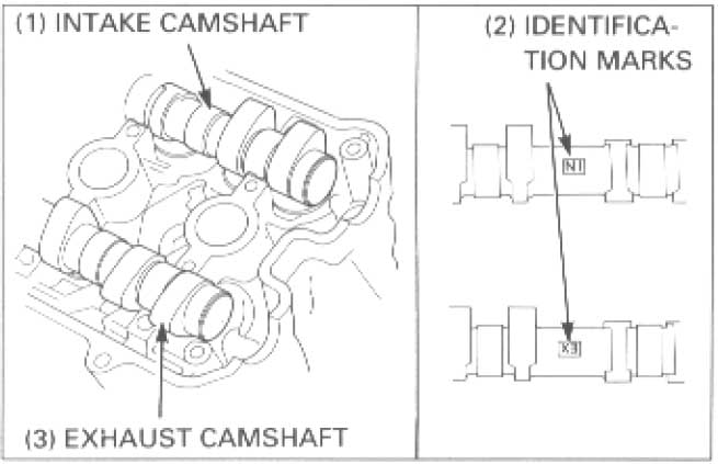
SORRY TO SAY BUT THE PHOTO OF THE INTAKE AND EXHAUST CAM LINE UP MARKS ARE WRONG
The identification marks IN/EX Have to be COMPLETELY LEVEL with the top surface of the cylinder head, that is with the cylinder valve cover gasket removed,as per the very first diagram.
It's tricky but I could let you know how I managed it after I had to replace shims if that's of any help,if the EX under mark is not parallel with the head surface, you WILL retard the exhaust timing and very most likely burn your exhaust valves,seats and guides!!
Ride safe,
Ant.

