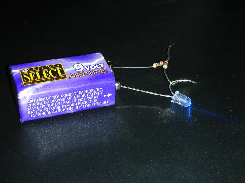
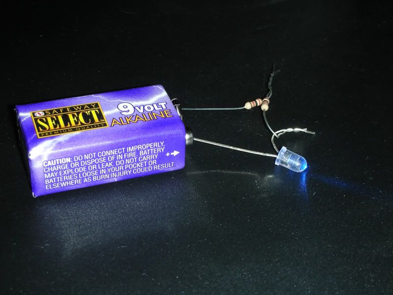
Soldering and resistors- what went wrong?
#11
Resistors are POLARITY free, btw..if you have a series circut..then the current will be the same through all devices, resistors will drop voltage..all the devices in the circut will have the same current flow through them, and depending on the resistance of each device, will determine what voltage drop it will have..but all the voltages in the circut HAVE to equal the total voltage..so, say you have a 12 volt battery (conveniently enough) and you connect a resistor in series ( so, a resistor with 1 of the leads on the positive and 1 on the negative, doesnt freaken matter witch way!! You will have a 12 volt drop across that resistor. if the resistor is say 220 ohms, then the current will be..( using Ohms law..of E=IR...) 12=Ix220 ....I = 12/220 ==54.5mA. I = 54.5mA. So the current flow of this particular circut is 54.5 mA
seris cct, is like a train...chooo chooo!! everything is connected after eachother..1 lead to the next.
parallel is where there's a split between 2 leads..or more than 1 path the current can flow.. so, with ought getting way complicated, remember --Current stays the same in a series circut, period. ( Kirchhoff's current and voltage laws)..go here is you want < facstaff.bucknell.edu/mastascu/eLessonsHTML/Basic/Basic5Kv.html >
Voltage stays the same in a parallel cct. -- Just don't go having combination ccts, then the calculator is coming out...and no one wants to see that mamma jamma..its summertime!!
Nikos, what do you mean by measuring the resistance through the opener, when its open, ( like an open cct, theres no current flow, but all the supply voltage is on that 'open' )?? I don't want to call you out, but I don't understand what your trying to say...it doesnt sound right, but your on the right track...I am a sparky so dont take offense!
#13
ORIGINAL: sUshI
Resistors are POLARITY free, btw..if you have a series circut..then the current will be the same through all devices, resistors will drop voltage..all the devices in the circut will have the same current flow through them, and depending on the resistance of each device, will determine what voltage drop it will have..but all the voltages in the circut HAVE to equal the total voltage..so, say you have a 12 volt battery (conveniently enough) and you connect a resistor in series ( so, a resistor with 1 of the leads on the positive and 1 on the negative, doesnt freaken matter witch way!! You will have a 12 volt drop across that resistor. if the resistor is say 220 ohms, then the current will be..( using Ohms law..of E=IR...) 12=Ix220 ....I = 12/220 ==54.5mA. I = 54.5mA. So the current flow of this particular circut is 54.5 mA
seris cct, is like a train...chooo chooo!! everything is connected after eachother..1 lead to the next.
parallel is where there's a split between 2 leads..or more than 1 path the current can flow.. so, with ought getting way complicated, remember --Current stays the same in a series circut, period. ( Kirchhoff's current and voltage laws)..go here is you want < facstaff.bucknell.edu/mastascu/eLessonsHTML/Basic/Basic5Kv.html >
Voltage stays the same in a parallel cct. -- Just don't go having combination ccts, then the calculator is coming out...and no one wants to see that mamma jamma..its summertime!!
Nikos, what do you mean by measuring the resistance through the opener, when its open, ( like an open cct, theres no current flow, but all the supply voltage is on that 'open' )?? I don't want to call you out, but I don't understand what your trying to say...it doesnt sound right, but your on the right track...I am a sparky so dont take offense!
#14
krusher, it shouldnt make a difference where you put the resistor in the circuit. the resistor will limit the current/voltage no matter if it is hooked up to the positive or negative source. components connected in series carry the same current as each other and each component experiences a voltage drop simultaneously, not one at a time.
try your experiment for yourself, it will be the same no matter where the resistor is, like sushi said. parallel is a little more complicated....
try your experiment for yourself, it will be the same no matter where the resistor is, like sushi said. parallel is a little more complicated....
#15
ORIGINAL: axsys
krusher, it shouldnt make a difference where you put the resistor in the circuit. the resistor will limit the current/voltage no matter if it is hooked up to the positive or negative source. components connected in series carry the same current as each other and each component experiences a voltage drop simultaneously, not one at a time.
try your experiment for yourself, it will be the same no matter where the resistor is, like sushi said. parallel is a little more complicated....
#16
#17
#18
ORIGINAL: amanc96
Actually, it will make a difference with an LED. The point of the resistor on an anode side of an LED instead of the cathode side is to limit the current through the LED to make sureyou don't burn it up.
ORIGINAL: axsys
krusher, it shouldnt make a difference where you put the resistor in the circuit. the resistor will limit the current/voltage no matter if it is hooked up to the positive or negative source. components connected in series carry the same current as each other and each component experiences a voltage drop simultaneously, not one at a time.
try your experiment for yourself, it will be the same no matter where the resistor is, like sushi said. parallel is a little more complicated....
krusher, it shouldnt make a difference where you put the resistor in the circuit. the resistor will limit the current/voltage no matter if it is hooked up to the positive or negative source. components connected in series carry the same current as each other and each component experiences a voltage drop simultaneously, not one at a time.
try your experiment for yourself, it will be the same no matter where the resistor is, like sushi said. parallel is a little more complicated....
#20
ORIGINAL: CbR_hEathen
why didnt you just save yourself all the trouble and just use the battery that was already in the opener?
why didnt you just save yourself all the trouble and just use the battery that was already in the opener?
I ended up getting a 12v remote and wired it to my highbeams. Works great!
(click here for a how-to on wiring it to your high-beam switch)


