When you click on links to various merchants on this site and make a purchase, this can result in this site earning a commission. Affiliate programs and affiliations include, but are not limited to, the eBay Partner Network.
Improving idle run and decrease alternator load at idle
I start this post because I haven been busy to improve the idle running of the bike.
Now I am quite new to the bike world but not to combustion engines. The first thing I noticed when I heard my bike running was the crappy idle of the engine.
An improvement was to clean the throttle bodies however this was not all.
Also I discovered the alternator paritially burned, which caused that the alternator only had two phases working, while the third was shorted to mass.
After fixing this the bike ran better but still crappy.
A big improvement to the idle run was exchanging the normal halogen bulbs (the 55W and the three 5W) for LED's. This reduced the power drawn at idle from a total of 70W to 28W.
Since this was a big improvement I started measuring noise at the battery with an oscilloscope.
At idle the noise was about 0,5V and when revving higher the noise got worse to about 3V.
In the bike there is a very important powerline (black white, with green dots) On this powerline are connected: the ignition, the injectors, the pair valves, the regulator/ rectifier reference line, fuel cut off relay, and fan control relay.
This line is fused with a 20A fuse. However the resistance of this fuse was quite high and putting a capacitor over the battery is useless because of this.
Therefore I connect the capacitor to the single polarity connector and a decent ground. However this will be done in a couple of days. When I have time.
The first picture shows the connector in the wiring diagram, the second picture the connector IRL.
The third picture shows the capacitor with 3 wires. a + and -. and a separate very thin wire with a resistor to charge the capacitor. This wire will be directly connected to the battery +.
The reason for this charging wire is to make sure that te capacitor does not violently charge over the fuse. I do not really know if this is the right approach but I think it is not a bad solution. I have to do some measurements to make sure it works.
The fourth picture is the capacitor mounted in the bike, next to the regulator/ rectifier.
thanks,
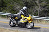
At the moment the bike is on a couple of wooden blocks to do maintenance on the swingarm.
I'm still waiting for all the dust seals to come in and after the swingarm is assembled I can remount the exhaust.
In between I also cleansed the throttle bodies so it is a work in progress.
I will update this as soon as there is progress.
The third picture shows the capacitor with 3 wires. a + and -. and a separate very thin wire with a resistor to charge the capacitor. This wire will be directly connected to the battery +.
The reason for this charging wire is to make sure that te capacitor does not violently charge over the fuse. I do not really know if this is the right approach but I think it is not a bad solution. I have to do some measurements to make sure it works.
The fourth picture is the capacitor mounted in the bike, next to the regulator/ rectifier.
to be continued.
I'm hoping that you mean that it will be some kind of fused connection.
Yes it is kind of fused, by using a 820 Ohm resistor and using a stupid thin wire.
However I think of using a diode to sort of separate the ignition circuit and using a much smaller capacitor next to the injectors.
the current state of my bike. So it might take some time before it runs again
 01-01-2022, 10:13 AM