Intergrated tail... NO Blinkers?
#1
 06-27-2009, 10:22 PM


Join Date: Apr 2007
Location: Dryden/Ludington, MI
Posts: 11
Likes: 0
Received 0 Likes
on
0 Posts
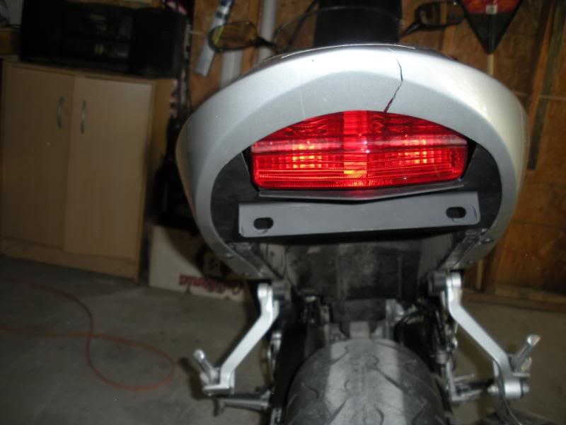
03 F41. Last yr I put on Hotbodies Flush mounts up front, only two wire setup. They were fast, but I didn't care. I just did a fender delete and wanted to loose the stalks so I bought a 3 wire to 2 wire converter and wired it in for a "do-it-yourself" intergrated tail. Brakes and running work, but the rear turn signals are blinking soooo fast you can't even tell. Front signals work as they did (still fast) and when I turn on a signal both R and L lights come on at the dash (at the same time). These are still the stock bulbs in the rear. I have triple checked the wiring and all is correct. Been searching the forum for awhile now and it seems to be started by the LEDs, but n ow that I removed 2 bulbs the system isn't pulling its power and I have two options to correct??? 1 is to install resistors and 2 is to swap out the flasher relay.
Questions for option 1:
If I just install the resistors on the front LEDs, should that fix it or do I need to install them on all 4? What size resistor do I need? I think its 8 ohm 20-25 watt? and where can I get them? Radio shack on only get me upto 10 watt? When I install them, do I put them inline on the positive or tap one end into pos and tap other into neg?
Questions for option 2:
Will just a relay change fix the problem? If so, what kind do I get? All the links to other relays are going to old ebay ads I cannot see. Can I get at Autozone or similar? Is this relay hard to get to on the bike?
Thanks for the help in advance......
#2
06-27-2009, 11:07 PM
Join Date: Apr 2007
Location: Dryden/Ludington, MI
Posts: 11
Likes: 0
Received 0 Likes
on
0 Posts
UPDATE:
I had some LED load stabilizers that I got from AutoZone and hooked them to the rear of the bike. One for right turn, one for left. The turn signlas now worked as they should, nice and slow. But when I hit the brake light the turns start to blink fast again. That is the only issue now. If I put another set of load stabilizers on the front signals, should that cure the fast blink with the brake on, or do I need to have it inline with the brake?
I had some LED load stabilizers that I got from AutoZone and hooked them to the rear of the bike. One for right turn, one for left. The turn signlas now worked as they should, nice and slow. But when I hit the brake light the turns start to blink fast again. That is the only issue now. If I put another set of load stabilizers on the front signals, should that cure the fast blink with the brake on, or do I need to have it inline with the brake?
#3
06-28-2009, 07:37 PM

Senior Member
Join Date: Mar 2009
Location: Marietta, Ohio
Posts: 533
Likes: 0
Received 0 Likes
on
0 Posts
Sounds like to me somethings hooked up wrong. You should only need one stabilizer for each side because the blinkers are connected to each other. Reason the blink together.. I don't believe your tail light should affect anything so id take a second look at it all. I got the same hotbodys up front and a integrated tail in the back, they blink fast but you can still see they are blinking and I have no stabalizer.
#4
06-28-2009, 11:47 PM

July 2008 ROTM
Join Date: Oct 2007
Location: Milwaukee
Posts: 3,002
Likes: 0
Received 0 Likes
on
0 Posts
Load stabilizers should go on the lights that the load is missing from, AKA your front turn signals. If you got a rear integrated wiring kit, it's using the stock incandescent brake lights for turn signals, which will have the proper resistance.
As xjoewhitex said, it sounds like your wiring is wrong somewhere. But I can't tell you where to fix it because you already mentioned changing it in like 3-4 places.
As xjoewhitex said, it sounds like your wiring is wrong somewhere. But I can't tell you where to fix it because you already mentioned changing it in like 3-4 places.
#5
06-29-2009, 10:47 AM

Member
Join Date: May 2009
Location: Portland, ME
Posts: 53
Likes: 0
Received 0 Likes
on
0 Posts
This is true, load stabalizers go on the front (unless you ever get led's for the back, then you wont need em).
If you did the "do-it-yourself" integrated tail thing from the how-to forum here, as I did last week, you probably missed the part about putting the diode in line with the signal wire from the front blinkers. The diode keeps the current from the brake signal from getting back to the front blinkers accidentally.
If you did the "do-it-yourself" integrated tail thing from the how-to forum here, as I did last week, you probably missed the part about putting the diode in line with the signal wire from the front blinkers. The diode keeps the current from the brake signal from getting back to the front blinkers accidentally.
#6
06-29-2009, 02:34 PM
Join Date: Apr 2007
Location: Dryden/Ludington, MI
Posts: 11
Likes: 0
Received 0 Likes
on
0 Posts
Wiring is 100% correct.
To test, I connected to stock turn signals to the intergrated tail 'brake/Turn" wire. With the "old" bulbs, tail light and LED up front all pulling power, the turn signals work as they should, they blink at stock form. When I disconnected the "old" signals, then I got the no blink situation as described. This tells me everything is hooked up correctly and that its a load issue. I ended up putting the load equilizer on the back because, well, that was already torn apart. With these on, the blinkers were slow as normal, but only sped up when I hit the brake. I don't think it would change a thing if I moved the equalizers up front. The relay is not smart enough to know which is pulling less current, the front or the back. It just knows how much should be going out total. As long as the equalizer is adding the lost amperage "in total", it doesn't matter where it goes in the circut, just as long as the relay thinks its putting out XXX amount of power not to trip the fast blink stage. I think the fast blink is being caused by the now "brake/turn" bulb needing less amperage to blink when the brake is appllied.
From looking around online, it seemd there would be a low current issue with the rear once intergrated even without the LEDs up front, and a load staiblizer would still be needed in the rear.
I kinda like it the way that it is. It's very eye-catching, which is what I want. I think if I put a set up resistors up fron that will make everything blink stock all the time. But, after doing more searching I found that the easiest fix is the flasher relay. I ordered that up last nite. Once that gets here I will remove the back equalizers and get my $12 back from Auto Zone .
.
To test, I connected to stock turn signals to the intergrated tail 'brake/Turn" wire. With the "old" bulbs, tail light and LED up front all pulling power, the turn signals work as they should, they blink at stock form. When I disconnected the "old" signals, then I got the no blink situation as described. This tells me everything is hooked up correctly and that its a load issue. I ended up putting the load equilizer on the back because, well, that was already torn apart. With these on, the blinkers were slow as normal, but only sped up when I hit the brake. I don't think it would change a thing if I moved the equalizers up front. The relay is not smart enough to know which is pulling less current, the front or the back. It just knows how much should be going out total. As long as the equalizer is adding the lost amperage "in total", it doesn't matter where it goes in the circut, just as long as the relay thinks its putting out XXX amount of power not to trip the fast blink stage. I think the fast blink is being caused by the now "brake/turn" bulb needing less amperage to blink when the brake is appllied.
From looking around online, it seemd there would be a low current issue with the rear once intergrated even without the LEDs up front, and a load staiblizer would still be needed in the rear.
I kinda like it the way that it is. It's very eye-catching, which is what I want. I think if I put a set up resistors up fron that will make everything blink stock all the time. But, after doing more searching I found that the easiest fix is the flasher relay. I ordered that up last nite. Once that gets here I will remove the back equalizers and get my $12 back from Auto Zone
.
#7
06-29-2009, 02:59 PM
Join Date: Apr 2007
Location: Dryden/Ludington, MI
Posts: 11
Likes: 0
Received 0 Likes
on
0 Posts
#8
06-29-2009, 03:46 PM
Member
Join Date: May 2009
Location: Portland, ME
Posts: 53
Likes: 0
Received 0 Likes
on
0 Posts
Ok, you should have a wire coming from each front blinker going to the relays right?
Instead of hooking that up to the signal wire (at the front blinkers) use the third wire (the one for the running lights, which you probably aren't using if you have led's). When you do this you may also have to swap the brake signal and rear turn signal wires going into each of the relays (i don't remember if i had to). This will eliminate some of the load balancing issue you are having, i forgot that i did this to mine. When you tap into the signal wire and have led's it causes problems where the signal doesn't last long enough for the relay to switch.
Once you do this, the blinkers will still blink fast, but you should have no problems when the brake is applied, at least I don't.
I have a wire diagram that I drew up at home, i can scan it and post if you want, let me know.
#10
06-29-2009, 04:17 PM
Join Date: Apr 2007
Location: Dryden/Ludington, MI
Posts: 11
Likes: 0
Received 0 Likes
on
0 Posts
I think once I swap out the stock relay for a LED relay, everything will work correctly. I don't see a reason to hook up the running lights to anything up front, or disconnecting and swapping rear turn signal wire with brake wires and crossing relays etc...... Thats is just causing way too much work that isn't needed.
Bottom line is the bike has a 3 wire setup (brake/running/Turn). This is the way alot of cars are wired now, I think to give the fast blink to let you know a light is out. If it didn't have the 3 wire setup, it couldn't tell. The converter I have takes the 3 wire and turns it into a 2 wire setup (brake & signal/running). Cars from back in the day came like this. The only problem with the two wire setup is it changes the load output, which the stock relay thinks a bulb is out due to the lower draw. By installing a variable load relay (like cars used to have with the 2 wire setup), the bike will not think a bulb is burned out and will work as it should. Even if it doesn't blink slow with the new relay I ordered ( http://www.customled.com/products/fl...sher_relay.htm ) I'm gonna leave it as it. I don't mind the fast blink, as I'd rather not rewire the entire bike.
ndf4i,
The converter is made by Hopkins towing solutions. Part number is 48845 It basically does what the guy built in the how-to section, your just buying it already done and ready togo.
http://www.hopkinstowingsolutions.co...verter_12.html
Here is where I bought it: http://www.autozone.com/autozone/cat...questid=799667
Very simple to wire up:
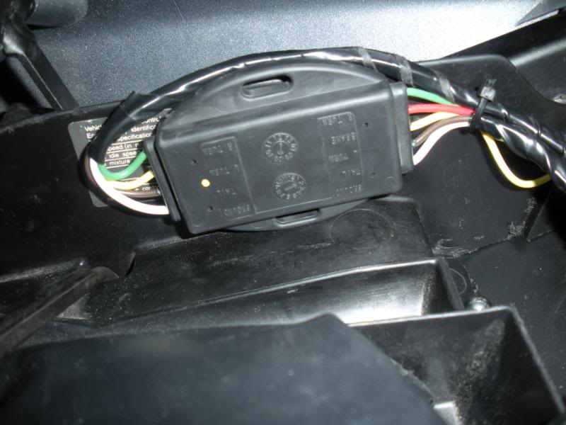
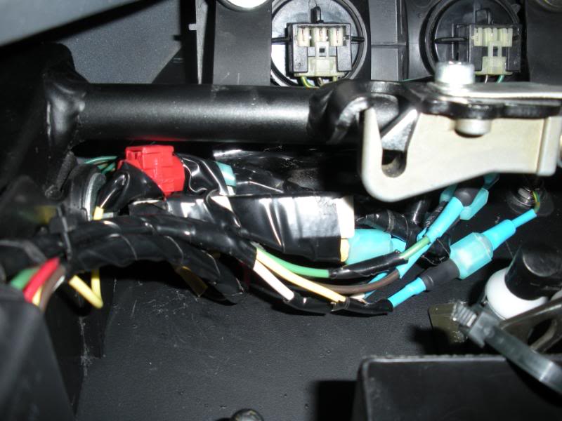
Cut the two 3-wire connectors for the tailight bulbs off about 3" from connectors. The 3 wires are G/Y(brake), G(ground) and Bl/Br(running). Tape of one of the 3 wire connectors, as you only need one of them. Cut the turn signal wires off a few inches from the connectors. Now here is the wiring
Bike -Converter (bike side)
Gr/Yl -Red BRAKE
Green -White GROUND
Bl/BR -Brown Running
Oragne -Yellow LEFT
Lt Blue -Green RIGHT
I used spade connectors to make easy connections.
Bike -Converter (Bulb side)
Gr/Yl -Yellow Left Bulb
Gr/Yl -Green Right Bulb
Green -White GROUND - Connects to both greens coming form each bulb
Bl/BR -Brown Running - Connects to both Blk/Br coming form each bulb
What I did with the bulb connector was hook a 1 spade connector to each gr/yellow wire, then I took both greens and twisted them together and put them in a single spade. I did the same thing for the Blk/br. This way you have the opposite connector on the "converter out" wire that will plug into only 1 connector.
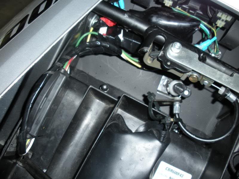
I don't have the LED relay as of yet, so I have a load equalizer hooked to the rear turn wires before the converter. I used a wire tap to hook to the Lt Blue and orange and then hooked the other end of the equalizer to the green wires that are next to the turn signals. If you don't use the load equalizers, the you will NOT use these to green ground wires. I just used them so I didn't have to tap into the common ground going into the converter.
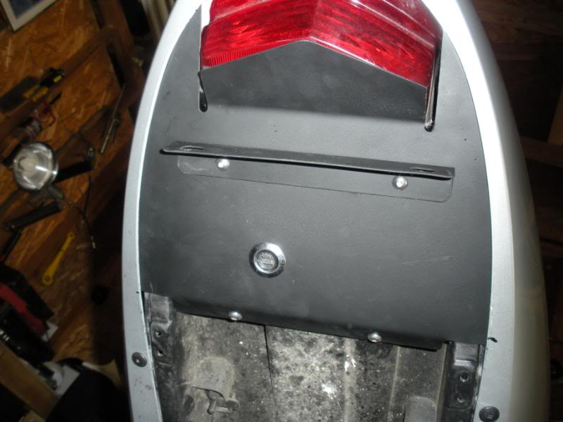
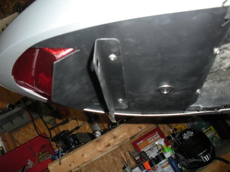
This pic kinda shows the spade connectors:
Bottom line is the bike has a 3 wire setup (brake/running/Turn). This is the way alot of cars are wired now, I think to give the fast blink to let you know a light is out. If it didn't have the 3 wire setup, it couldn't tell. The converter I have takes the 3 wire and turns it into a 2 wire setup (brake & signal/running). Cars from back in the day came like this. The only problem with the two wire setup is it changes the load output, which the stock relay thinks a bulb is out due to the lower draw. By installing a variable load relay (like cars used to have with the 2 wire setup), the bike will not think a bulb is burned out and will work as it should. Even if it doesn't blink slow with the new relay I ordered ( http://www.customled.com/products/fl...sher_relay.htm ) I'm gonna leave it as it. I don't mind the fast blink, as I'd rather not rewire the entire bike.
ndf4i,
The converter is made by Hopkins towing solutions. Part number is 48845 It basically does what the guy built in the how-to section, your just buying it already done and ready togo
. http://www.hopkinstowingsolutions.co...verter_12.html
Here is where I bought it: http://www.autozone.com/autozone/cat...questid=799667
Very simple to wire up:
Cut the two 3-wire connectors for the tailight bulbs off about 3" from connectors. The 3 wires are G/Y(brake), G(ground) and Bl/Br(running). Tape of one of the 3 wire connectors, as you only need one of them. Cut the turn signal wires off a few inches from the connectors. Now here is the wiring
Bike -Converter (bike side)
Gr/Yl -Red BRAKE
Green -White GROUND
Bl/BR -Brown Running
Oragne -Yellow LEFT
Lt Blue -Green RIGHT
I used spade connectors to make easy connections.
Bike -Converter (Bulb side)
Gr/Yl -Yellow Left Bulb
Gr/Yl -Green Right Bulb
Green -White GROUND - Connects to both greens coming form each bulb
Bl/BR -Brown Running - Connects to both Blk/Br coming form each bulb
What I did with the bulb connector was hook a 1 spade connector to each gr/yellow wire, then I took both greens and twisted them together and put them in a single spade. I did the same thing for the Blk/br. This way you have the opposite connector on the "converter out" wire that will plug into only 1 connector.
I don't have the LED relay as of yet, so I have a load equalizer hooked to the rear turn wires before the converter. I used a wire tap to hook to the Lt Blue and orange and then hooked the other end of the equalizer to the green wires that are next to the turn signals. If you don't use the load equalizers, the you will NOT use these to green ground wires. I just used them so I didn't have to tap into the common ground going into the converter.
This pic kinda shows the spade connectors:
Last edited by Salmonbum; 06-29-2009 at 04:49 PM.