
F1 code fuel injector problem.


Thread Starter
|
Member
Joined: May 2024
Posts: 93
Likes: 4
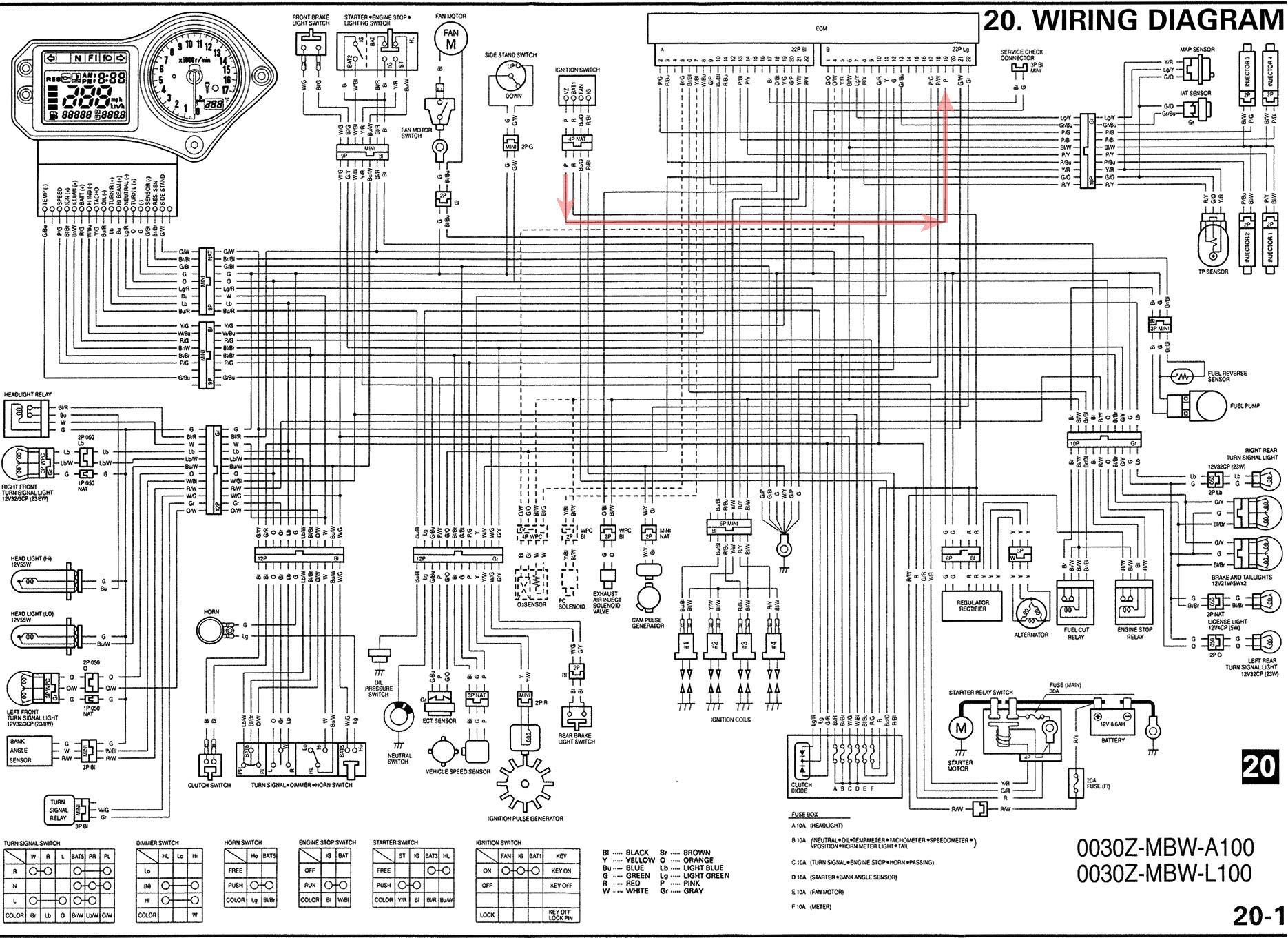
Here's wiring diagram, showing NO connection of PINK to any other wire.
Given how many non-standard things you've found with this harness. I recommend removing whole thing from bike:
1. spread it out on large 4x8 sheet of plywood
2. unravel all wraps and tape
3. verify every single wire has end-points that connect to destinations shown by manual. And ONLY those end-points, nothing else anywhere!
4. verify again every single wire is run according to manual.
5. triple check again, that every single wire matches what you see in manual. Nothing missing, nothing extra.
6. then put it back on bike, but before connecting ANYTHING, just battery & ground.
verify above tests with ignition-switch only, ignition-switch connected to harness, that you've got exactly 9.0v at pink-wire at ECU connector. DO NOT bring that ECU back out of bank box until you've confirmed these measurements!!!
Thanks.

Senior Member
Joined: May 2011
Posts: 1,988
Likes: 439
From: Mesa, AZ
You’re doing great job, you’re almost there! 
Yeah, no O2 sensor or PC solenoid for you. Ignore stuff that’s inside dashed lines. It’s not required unless you have CA ECU with extra lines for those components. And they only come into play with warmed-up engine. Definitely nothing to do with ECU priming pump and starting bike.
Yeah, no O2 sensor or PC solenoid for you. Ignore stuff that’s inside dashed lines. It’s not required unless you have CA ECU with extra lines for those components. And they only come into play with warmed-up engine. Definitely nothing to do with ECU priming pump and starting bike.
Last edited by dannoxyz; Jun 11, 2024 at 10:37 PM.
Thread Starter
|
Member
Joined: May 2024
Posts: 93
Likes: 4
You�re doing great job, you�re almost there!
Yeah, no O2 sensor or PC solenoid for you. Ignore stuff that�s inside dashed lines. It�s not required unless you have CA ECU with extra lines for those components. And they only come into play with warmed-up engine. Definitely nothing to do with ECU priming pump and starting bike.
Yeah, no O2 sensor or PC solenoid for you. Ignore stuff that�s inside dashed lines. It�s not required unless you have CA ECU with extra lines for those components. And they only come into play with warmed-up engine. Definitely nothing to do with ECU priming pump and starting bike.
Battery voltage 13.0v. pink wire with ignition on 11.75v. I thought the zener diode was supposed to convert voltage to 9v. Could I have gotten a bad ignition from Honda?
Thread Starter
|
Member
Joined: May 2024
Posts: 93
Likes: 4

Senior Member
Joined: May 2011
Posts: 1,988
Likes: 439
From: Mesa, AZ
That’s correct test by itself. Send power in on red wire. Then measure outout on red/b wire and pink.
Nah, diode’s fried by being connected to red/b and blk/wht power wires on outlut side. Diode is not regulator, it does fixed -3.9v drop from input. So 13v -3.9=9.1v output. But as they get fried, voltage drop gets smaller and smaller.
As test, measure voltage on solder blobs holding diode on.
Nah, diode’s fried by being connected to red/b and blk/wht power wires on outlut side. Diode is not regulator, it does fixed -3.9v drop from input. So 13v -3.9=9.1v output. But as they get fried, voltage drop gets smaller and smaller.
As test, measure voltage on solder blobs holding diode on.
Last edited by dannoxyz; Jun 13, 2024 at 12:11 AM.
Thread Starter
|
Member
Joined: May 2024
Posts: 93
Likes: 4
That�s correct test by itself. Send power in on red wire. Then measure outout on red/b wire and pink.
Nah, diode�s fried by being connected to red/b and blk/wht power wires on outlut side. Diode is not regulator, it does fixed -3.9v drop from input. So 13v -3.9=9.1v output. But as they get fried, voltage drop gets smaller and smaller.
As test, measure voltage on solder blobs holding diode on.
Nah, diode�s fried by being connected to red/b and blk/wht power wires on outlut side. Diode is not regulator, it does fixed -3.9v drop from input. So 13v -3.9=9.1v output. But as they get fried, voltage drop gets smaller and smaller.
As test, measure voltage on solder blobs holding diode on.
Thanks
Thread Starter
|
Member
Joined: May 2024
Posts: 93
Likes: 4
So what do you think we try next?
Thread Starter
|
Member
Joined: May 2024
Posts: 93
Likes: 4
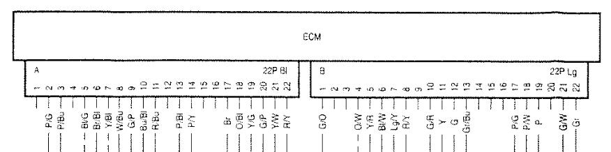
So I finally went through the wiring harness. Checked every wire and connection. All were good in place and good continuity with no corrosion. New ignition switch tested 9.7 volts on pink wire with kill switch on and off. Still no fuel pump prime. I installed jumper wire on fuel relay brown and bl/w wire and pump will prime with kill switch on. One confusion thing I found on the black ECU plug though. At number 16 slot which on wiring diagram shows no wire connected. On mine is has a green ground wire there. I checked it and it has good continuity just wondering why it doesn't show being there on the diagram? I guess this has nothing to do with anything but was wondering?
So what do you think we try next?
So what do you think we try next?
Senior Member
Joined: May 2011
Posts: 1,988
Likes: 439
From: Mesa, AZ
So I finally went through the wiring harness. Checked every wire and connection. All were good in place and good continuity with no corrosion. New ignition switch tested 9.7 volts on pink wire with kill switch on and off. Still no fuel pump prime. I installed jumper wire on fuel relay brown and bl/w wire and pump will prime with kill switch on. One confusion thing I found on the black ECU plug though. At number 16 slot which on wiring diagram shows no wire connected. On mine is has a green ground wire there. I checked it and it has good continuity just wondering why it doesn't show being there on the diagram? I guess this has nothing to do with anything but was wondering?
So what do you think we try next?
So what do you think we try next?
Measure resistance between that grn ECU connector wire to chassis-ground, ohms = ???
Is there anything in Lg connector at #12 where grn wire is supposed to go?
If not, move grn wire to that location.
Also verify remaining wires on ECU connector is what they're supposed to be:
Last edited by dannoxyz; Jul 1, 2024 at 07:12 PM.