
RC51 Gauge Swap DIY (in progress)
#1
 04-27-2011, 02:54 PM


Alright guys, I've had the parts for this for a few months now. I was recently laid off thanks to high gas prices, so I've got plenty of time to work on the bike at the moment. This is will be a step by step DIY on how to Wire and Mount a RC51 cluster to an F4 with an F4i body conversion. I will be posting pics later as I'm still working on it. Thought I would start the write up while the bike is on the battery charger.
There has been one hang up so far as wiring goes, which I'm about 90% certain I will have solved once I get the battery charged up. Apparently unlike most other Honda motorcycles the tachometer pulse read by the cluster is (+) instead of (-)! The RC51 cluster has a converter unit piggy backed off the ECM, that (as far as my electronics background can tell) supplies a digital counter a positive signal within the cluster. More on this later! (hopefully good news)
Wiring is otherwise similar to the F4i gauge swap with simply matching up the wires from the RC51 Harness to the F4:
Function F4 RC51
Temp green/blu green/blu
Speed pink/green pink/green
Ign (+) Black/brown Black/brown
20 km soleniod Pink/yellow (connect to ground {green})
Illum (+) Black/brown Black/brown (connect with IGN+)
Batt (cont 12+) Red Red/green
Turn (R+) Light blue light blue
hi beam Blue blue
Neutral LtGRN/Red LTGRN/Red
Oil (-) Blue/Red Blue/Red
Tach (-) yellow/green (still working this out)
Ground (-) x2 Green Green (wire both connections to one)
Sensor (-) x2 Green/BLK Green/BLK (same as above)
Turn (L+) Orange Orange
Reserve Sensor Brwn/BLK Brwn/BLK
I'll double check all those here in a minute to verify they are accurate.
As far as the tach signal goes I think I have that nailed down. I have been trying different things as far as where I can get a signal from. First tried the (-) Yellow/White from coming from the ignition pulser. After a cigarette and some coffee it dawned on me that both signals I had tried were negative pulses. I then proceeded to try the positive side of the ignition pulser (yellow). This so far resulted in a steady tach reading around 6000rpm... my bike normal idles around 1300ish. Since the Ignition pulser is sending out a pulse for every single time a spark is needed it should let the counter inside the cluster read 4x what it should. I'm going to attempt to piggy back off of one of the coil positive signals, since the ecm has a separate output for cylinder which "SHOULD" effectively reduce the reading to 1/4 of what it was before. Crossing my fingers here!
#2
04-27-2011, 03:59 PM
update... after trying a single wire off of one coil I effectively got 1/2 rpm reading on the tach... So... thinking i need some sort way to add the pulses of two coils to get what I need to get the tack to read effectively. After some Googling, I came across a DIY adapter for tachs that read 1/2 rpm on VStar motorcycles. So now i'm off to the local radio shack to purchase some resistors and some diodes to do this.
Also solved my charging problem! I had a bad reg/rect... was charging the bike at 15-16v at 3k or so... new regulator is putting out a nice 14.2v The old rectifier had actually exploded a lil bit!
Also solved my charging problem! I had a bad reg/rect... was charging the bike at 15-16v at 3k or so... new regulator is putting out a nice 14.2v
The old rectifier had actually exploded a lil bit!
#4
04-28-2011, 12:46 AM

Senior Member
Join Date: Apr 2010
Location: Chicago, IL
Posts: 484
Likes: 0
Received 0 Likes
on
0 Posts
you might be able to wrap the RPM cable around the plug, it's a normal thing you do with aftermarket gauges like koso... or there's something called type b connector which basically splices the rpm cable into the ingitors and back into the ignitors... another thing you do with aftermarket gauges.
#5
04-28-2011, 04:49 AM
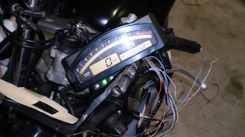
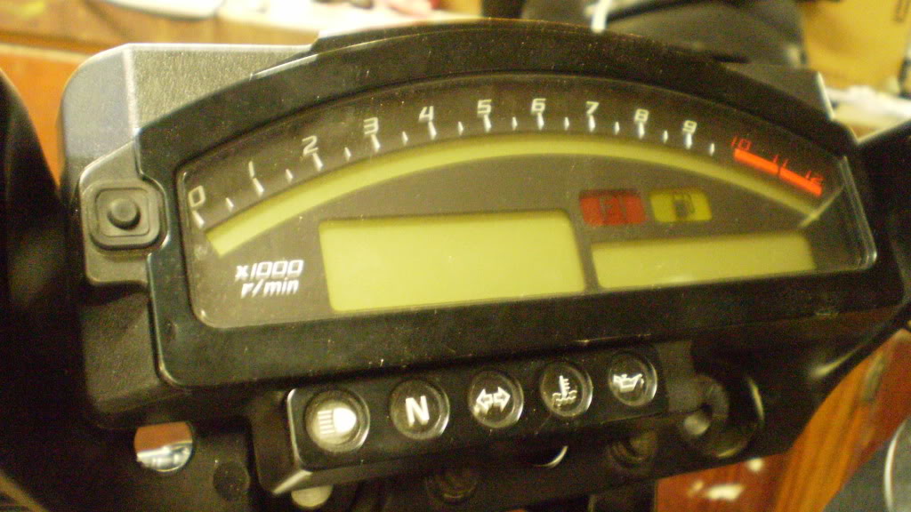
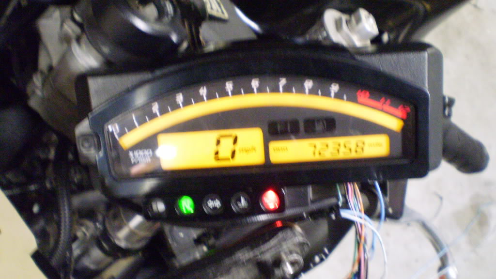
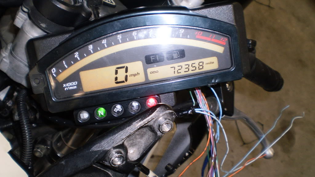
56k beware.... ok after 13.5 hrs in the garage working... it's done! The only thing I have yet to test is the speedometer (Monsoon style rain currently). I will have to swap over to the F4i temperature sensor at a later date as the temp starts around 220* cold and then peaks at 270* after a short time which makes the Temp warning light also come on. That will be a project for a later date as I know that my bike doesn't over heat (or I can at least tell when it needs parked on a hot day).
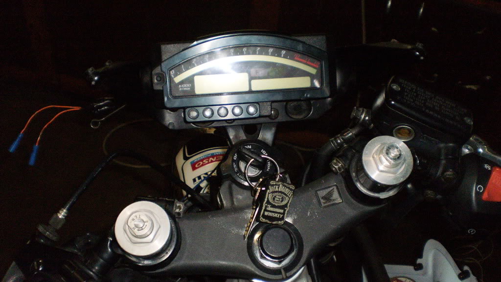
Out with the old in with the new!
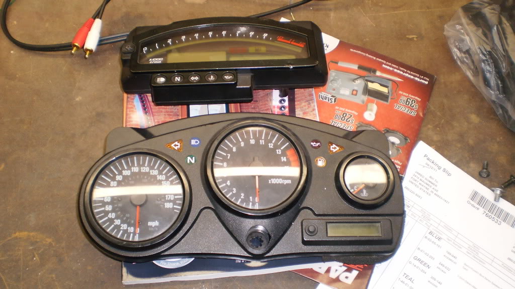
First off a few revisions to the wiring:
The High beam is blue (f4) - Blue/Black (RC51)
FI which is White/blue is not used and can just be taped up.
there is another one that has additional color, but it's 4:17am, and my note pad is in the garage. Through the process of elimination or by picture reference you can figure it out.
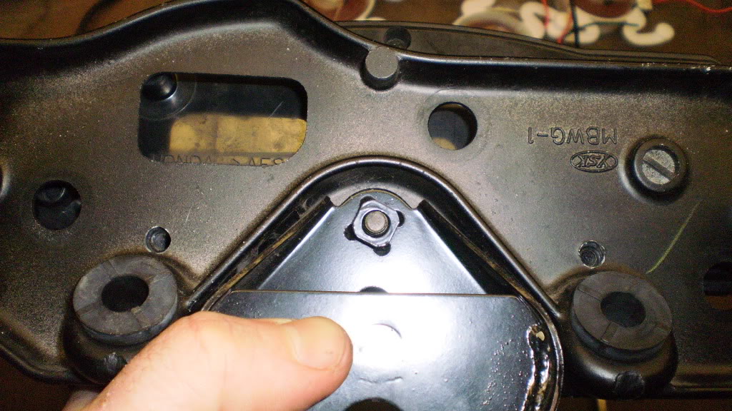
Here we go obviously you get down to just the fairing stay. Now I've learned a LONG time ago... you can always make a wire shorter, but you can't make it longer with out adding a connection. When trouble shooting electronics it ALWAYS makes it easier to have a long continuous wire as opposed to a few shorter wires cobbled together. Taking that in mind.
Step #1 Remove pins and wires from oem plug. (A trick is to cut away some of the outer plug then use a Eye glass screw driver to pry back the flat retaining clips holding the female pins in.) I'll show you why I did this later. Disassemble the RC51 harness and CUT OFF the main Gray connector and toss it vigorously towards the garbage can. Remove the tape and shrink wrap, so that you can move the wire around easily. Strip roughly 3/8" of the ends of all the RC51 wires ONLY! The gauges of the wires on both harness are the same, so simply (and carefully) twist the ends of each wire of the gauge harness, and insert them into there respective mate. No need for crimp style connectors, because you can lightly crimp the female pins down on to the wires (although make sure everything is working first), then solder the connections. Applying a piece of electrical tape to cover the connection, about 1.5" per connection will do as you don't want make it to bulky.
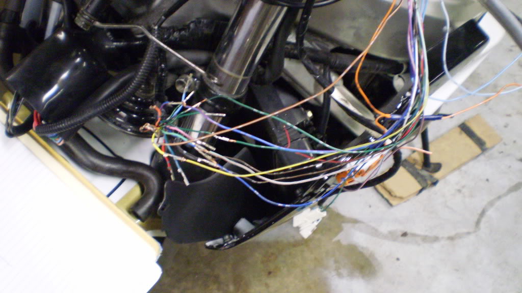
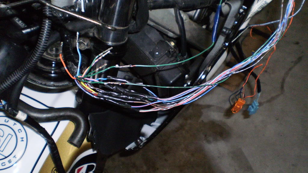
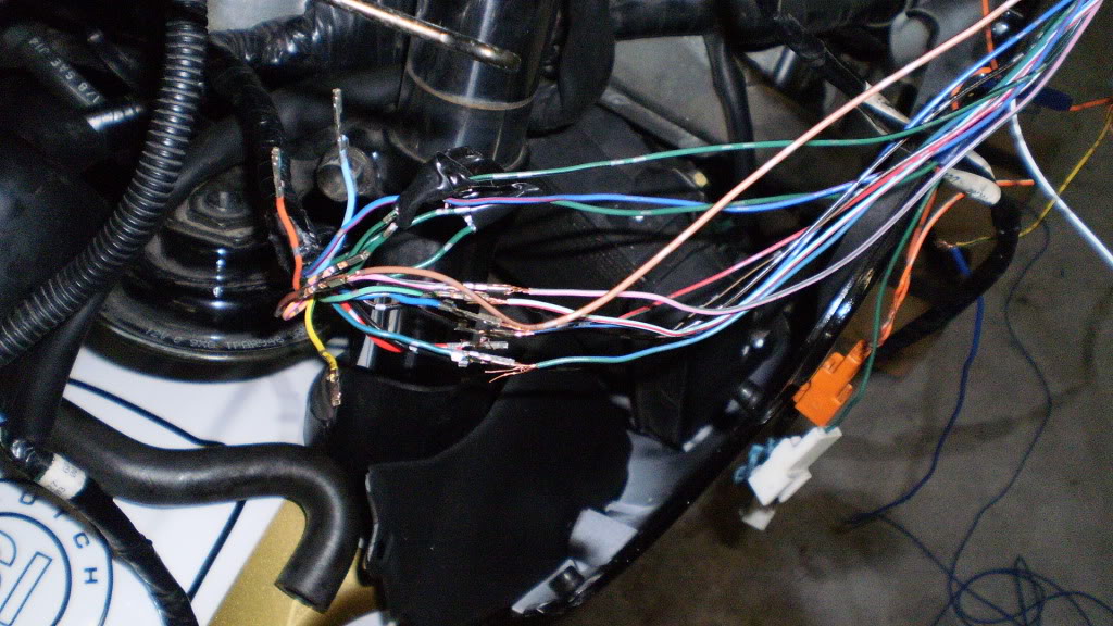
Step #2 For the Tach Signal wire cut a piece of 14-18g wire that is roughly 6ft long and attach it to the connection to the RC51 harness. The F4 connection will just be taped up and unused. Remember to solder the 20km/h solenoid wire to ground (solid green). After all your connections are solder and covered. Re-check gauge functionality... Everything should be working except the tach and you should get a temp reading similar to what I was getting if you have not swapped to the F4i temp sensor. I can not stress doing checks often enough as it makes it so much easier if you do something wrong or just plain forget. Now it's time to make it purty! Use the shrink wrap tube that you pulled off of the RC51 harness earlier and cut it in half. This will make it easier to work on down the road if you don't use all electrical tape (less sticky).
Step #3 Are we having fun yet? Time to get in the car/truck and head to your local RadioShack! You need to grab the following : 2x 1N4007 Diodes (4005-4007 will work, i used 4005's) ; 2x 100k ohm resistors 1/2watt 5% tolerance (they come in packs of 5). This will set you back $2+uncle sam. As mentioned earlier, I got the tach to read only 1/2 rpm. So we now get to build a tach adapter... cheapest I found online for these is $13+shipping pre-made from Schnitz Racing near here. For the electrically challenged let me tell you what we are doing here. Basically we need a 2 pulse/cycle signal sent to the tach in order for it to read. The one sent by your F4 ECM doesn't have enough voltage to properly communicate with the digital counters inside the RC51 cluster. By piggy backing of the negative sides of any 2 of the four IGN wires located on your ECM we get our 2 pulse/cycle signal. You can't just connect a piece of wire though as doing so could damage your ECM, your coils, electronics, and lord knows what else. The Diodes only let current flow one way, so this solves our problem. The Resistors are place in parallel with each diode and tied together at one end.
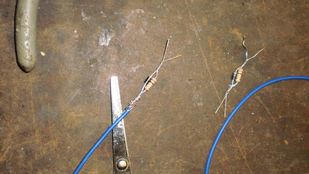
ok look closely at the pic, I actually made the adapter wrong the first time. Put the two leads that you piggy back into the ECM on the ends that silver!
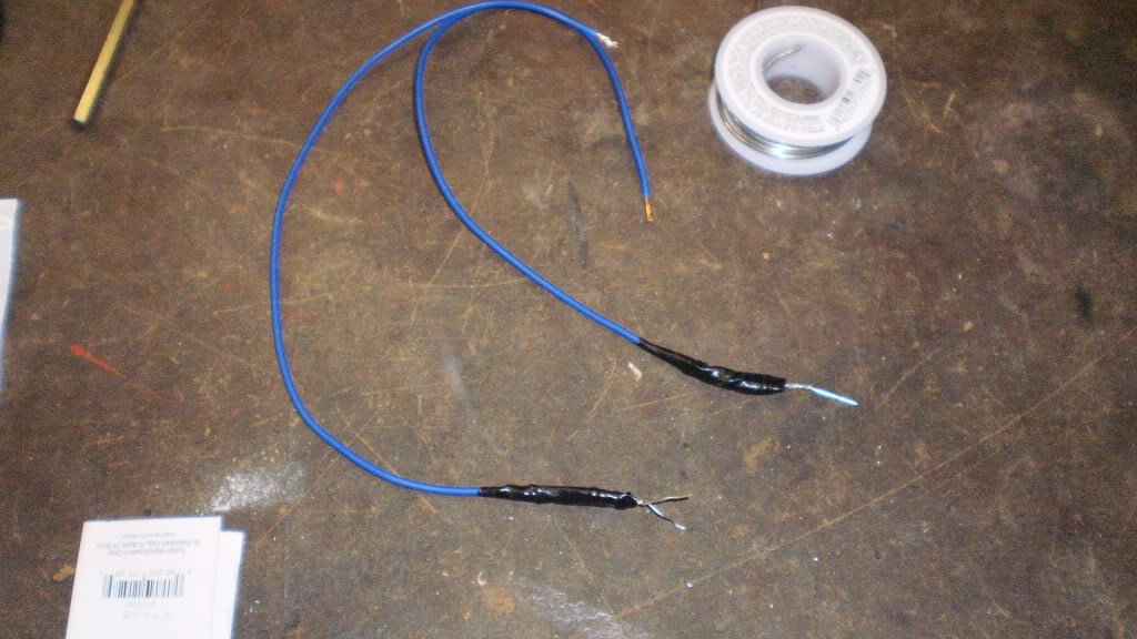
Then attach the black ends together and solder on a 6-8" lead with a connector of your choice.
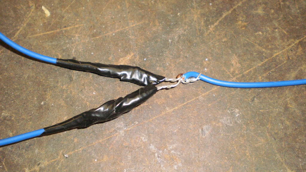
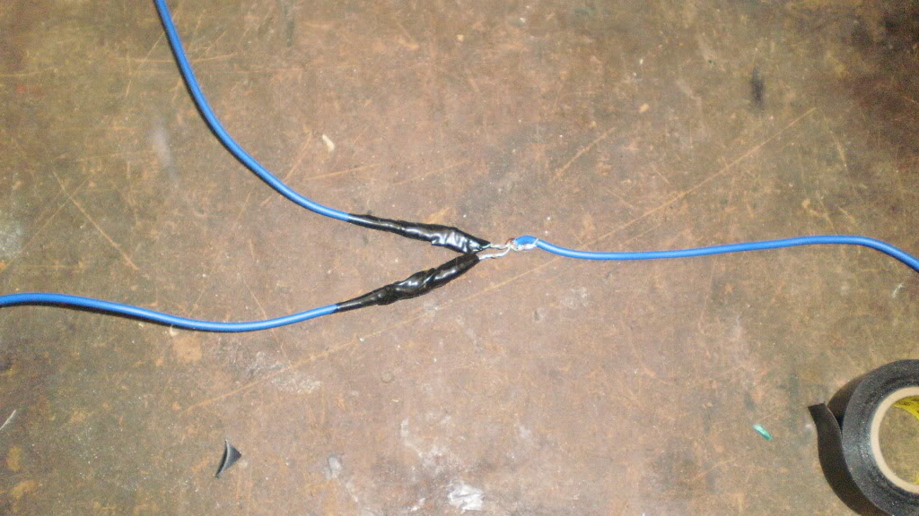
Choose your two IGN signal wires and carefully remove some of the sheath to expose some wire. I chose Red/blue and Blue/black. Solder the end of each one of your two tach adapter leads to a wire. Tape and stick it up under your subframe tray.
Re-check your gauge! If all is good take that really long wire and route it along your main body harness... (take your tank off).
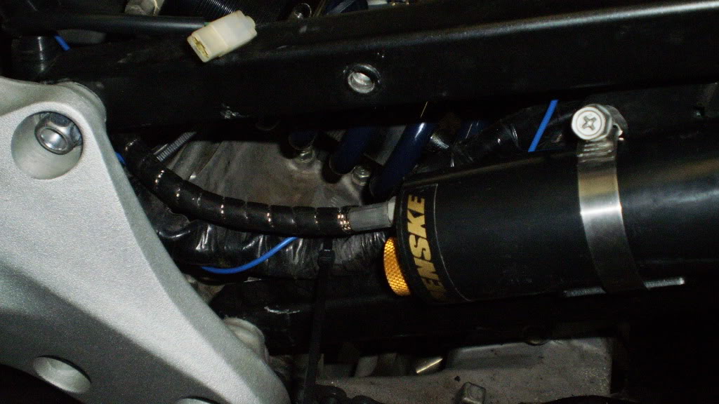
While I had the tank off I decided to put on my Penske shock.

Step#4 Ok all the really tedious stuff is out of the way... Take your gauge, put it plug side UP on a piece of poster board, and trace the outline. Mark the centers horizontally and vertically of your 3 mount holes and the outer limits of the plug. Remove gauge. Using a square find your centers for your holes and connect the lines for the plug hole. You've just made a mounting template for an RC51 gauge. Cut it out no remember this is backwards... so the side you just marked needs to face the fairing stay.
There is not much fudge room for mounting this however I did manage to get mine about 1/8" over towards one side. I'll just chock that up to not having a drill press. Pierce centers and corners of the 3 holes and connector area, then tape it to the stay. Use a punch on the mount holes to give your bit a good start. OH Yeah tip remove the stay before you drill or this might happen.
Drill out the 2 bottom holes first to make sure you get it level.
I used a 1/4" drill bit and it was perhaps a little big, but will give you some room for hole placement accuracy. Check alignment of holes.
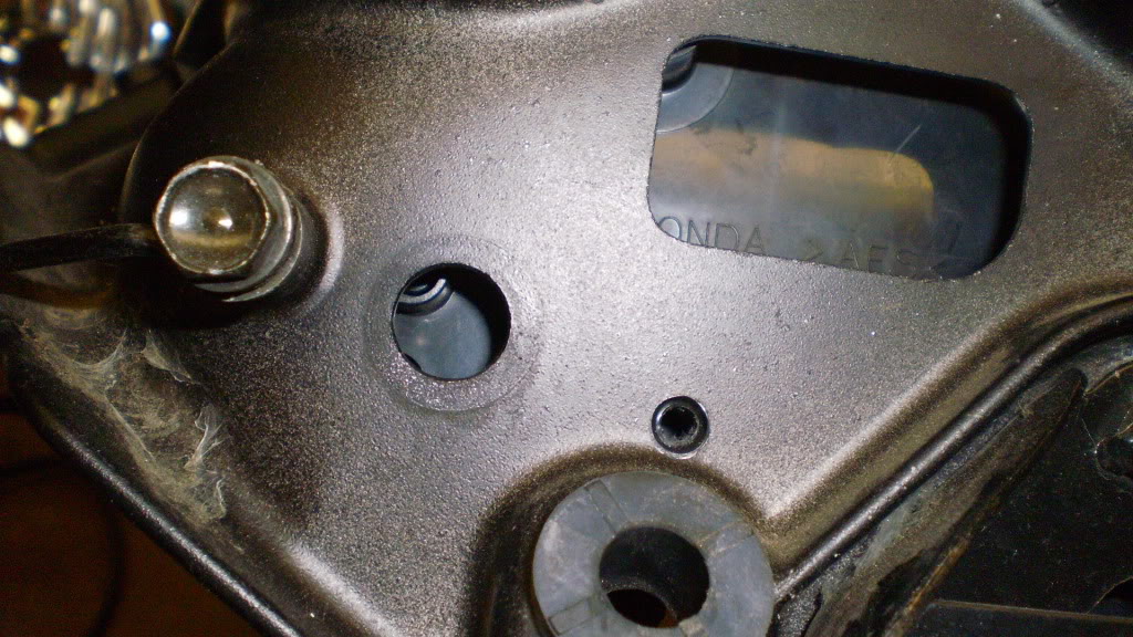
Repeat process with the 3rd mount hole and connector hole. Re-install fairing stay after de-burring the connector hole. Route plug connector through stay and attach to gauge. Attach gauge using factory supplied screws. VIOLA! Your done! Put the rest of your bike back together and ride!


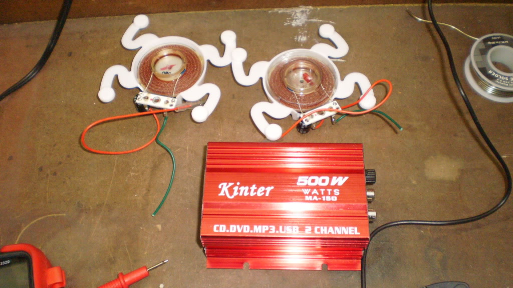
On tomorrow's to-do list... put my headlights back to stock and wire in these!
Dayton audio Sound Exciters and a Flea-bay t-amp...
Well been about 1.5 hrs writing this up. I'm off to eat and get a quick nap in before an appointment tomorrow. Comments and questions appreciated.
-Jae-
Out with the old in with the new!
First off a few revisions to the wiring:
The High beam is blue (f4) - Blue/Black (RC51)
FI which is White/blue is not used and can just be taped up.
there is another one that has additional color, but it's 4:17am, and my note pad is in the garage. Through the process of elimination or by picture reference you can figure it out.
Here we go obviously you get down to just the fairing stay. Now I've learned a LONG time ago... you can always make a wire shorter, but you can't make it longer with out adding a connection. When trouble shooting electronics it ALWAYS makes it easier to have a long continuous wire as opposed to a few shorter wires cobbled together. Taking that in mind.
Step #1 Remove pins and wires from oem plug. (A trick is to cut away some of the outer plug then use a Eye glass screw driver to pry back the flat retaining clips holding the female pins in.) I'll show you why I did this later. Disassemble the RC51 harness and CUT OFF the main Gray connector and toss it vigorously towards the garbage can. Remove the tape and shrink wrap, so that you can move the wire around easily. Strip roughly 3/8" of the ends of all the RC51 wires ONLY! The gauges of the wires on both harness are the same, so simply (and carefully) twist the ends of each wire of the gauge harness, and insert them into there respective mate. No need for crimp style connectors, because you can lightly crimp the female pins down on to the wires (although make sure everything is working first), then solder the connections. Applying a piece of electrical tape to cover the connection, about 1.5" per connection will do as you don't want make it to bulky.
Step #2 For the Tach Signal wire cut a piece of 14-18g wire that is roughly 6ft long and attach it to the connection to the RC51 harness. The F4 connection will just be taped up and unused. Remember to solder the 20km/h solenoid wire to ground (solid green). After all your connections are solder and covered. Re-check gauge functionality... Everything should be working except the tach and you should get a temp reading similar to what I was getting if you have not swapped to the F4i temp sensor. I can not stress doing checks often enough as it makes it so much easier if you do something wrong or just plain forget. Now it's time to make it purty! Use the shrink wrap tube that you pulled off of the RC51 harness earlier and cut it in half. This will make it easier to work on down the road if you don't use all electrical tape (less sticky).
Step #3 Are we having fun yet? Time to get in the car/truck and head to your local RadioShack! You need to grab the following : 2x 1N4007 Diodes (4005-4007 will work, i used 4005's) ; 2x 100k ohm resistors 1/2watt 5% tolerance (they come in packs of 5). This will set you back $2+uncle sam. As mentioned earlier, I got the tach to read only 1/2 rpm. So we now get to build a tach adapter... cheapest I found online for these is $13+shipping pre-made from Schnitz Racing near here. For the electrically challenged let me tell you what we are doing here. Basically we need a 2 pulse/cycle signal sent to the tach in order for it to read. The one sent by your F4 ECM doesn't have enough voltage to properly communicate with the digital counters inside the RC51 cluster. By piggy backing of the negative sides of any 2 of the four IGN wires located on your ECM we get our 2 pulse/cycle signal. You can't just connect a piece of wire though as doing so could damage your ECM, your coils, electronics, and lord knows what else. The Diodes only let current flow one way, so this solves our problem. The Resistors are place in parallel with each diode and tied together at one end.
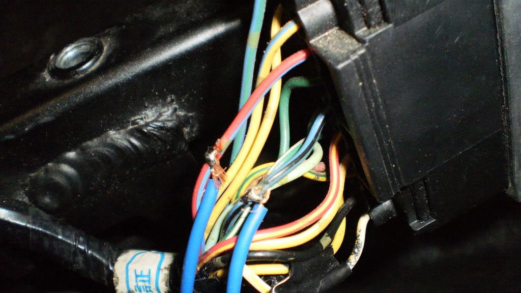
ok look closely at the pic, I actually made the adapter wrong the first time. Put the two leads that you piggy back into the ECM on the ends that silver!
Then attach the black ends together and solder on a 6-8" lead with a connector of your choice.
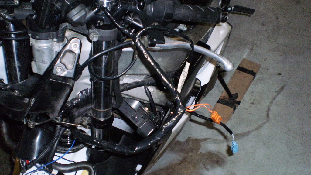
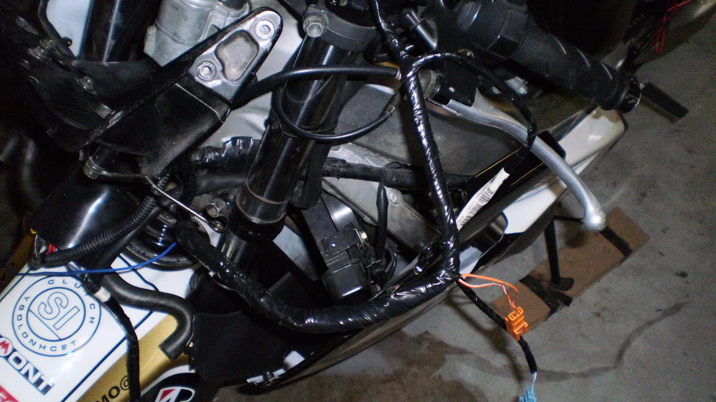
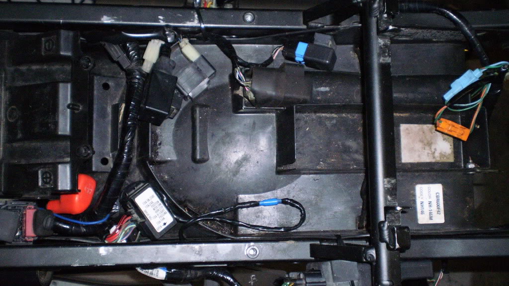
Choose your two IGN signal wires and carefully remove some of the sheath to expose some wire. I chose Red/blue and Blue/black. Solder the end of each one of your two tach adapter leads to a wire. Tape and stick it up under your subframe tray.
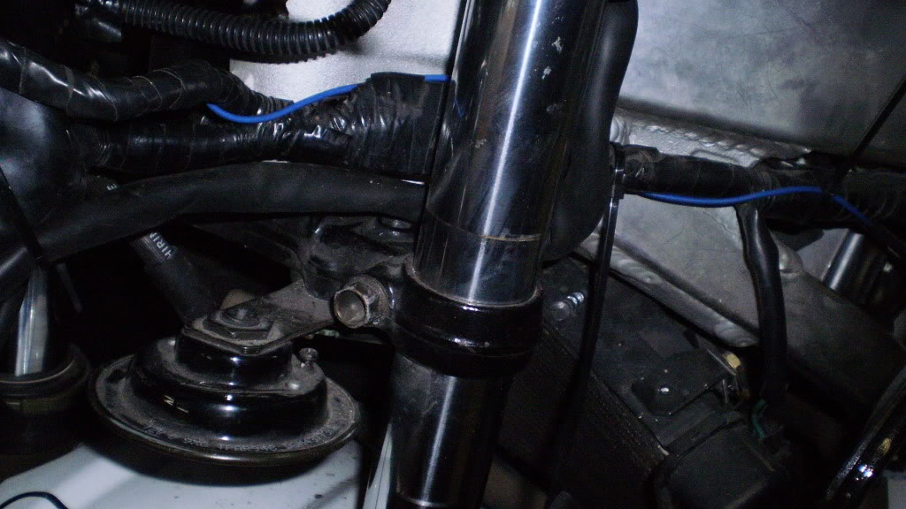
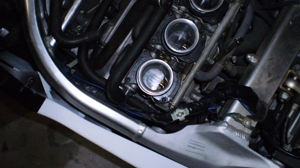
Re-check your gauge! If all is good take that really long wire and route it along your main body harness... (take your tank off).
While I had the tank off I decided to put on my Penske shock.
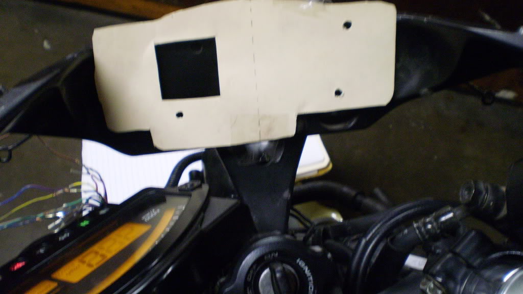
Step#4 Ok all the really tedious stuff is out of the way... Take your gauge, put it plug side UP on a piece of poster board, and trace the outline. Mark the centers horizontally and vertically of your 3 mount holes and the outer limits of the plug. Remove gauge. Using a square find your centers for your holes and connect the lines for the plug hole. You've just made a mounting template for an RC51 gauge. Cut it out no remember this is backwards... so the side you just marked needs to face the fairing stay.
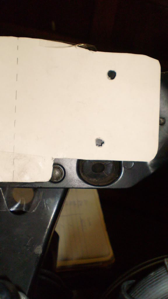
There is not much fudge room for mounting this however I did manage to get mine about 1/8" over towards one side. I'll just chock that up to not having a drill press. Pierce centers and corners of the 3 holes and connector area, then tape it to the stay. Use a punch on the mount holes to give your bit a good start. OH Yeah tip remove the stay before you drill or this might happen.
Drill out the 2 bottom holes first to make sure you get it level.
I used a 1/4" drill bit and it was perhaps a little big, but will give you some room for hole placement accuracy. Check alignment of holes.
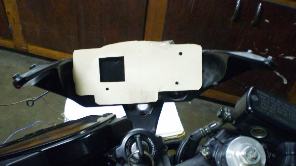
Repeat process with the 3rd mount hole and connector hole. Re-install fairing stay after de-burring the connector hole. Route plug connector through stay and attach to gauge. Attach gauge using factory supplied screws. VIOLA! Your done! Put the rest of your bike back together and ride!
On tomorrow's to-do list... put my headlights back to stock and wire in these!
Dayton audio Sound Exciters and a Flea-bay t-amp...
Well been about 1.5 hrs writing this up. I'm off to eat and get a quick nap in before an appointment tomorrow. Comments and questions appreciated.
-Jae-
#6
04-28-2011, 03:30 PM

Senior Member
Join Date: Nov 2010
Location: Nyon, Switzerland
Posts: 114
Likes: 0
Received 0 Likes
on
0 Posts
#7
04-29-2011, 12:34 PM

#9
04-29-2011, 03:34 PM
Senior Member
Join Date: Nov 2010
Location: Nyon, Switzerland
Posts: 114
Likes: 0
Received 0 Likes
on
0 Posts
#10
04-30-2011, 12:22 AM
@Denfro - that was just the size of the pistons I got off ebay. Unfortunately just got her back together, so no pics of the air ducts. I just cut off the expansion chambers and sealed them back up so they would work with the F4i body work.
@cuetip - do some hunting and waiting on ebay... including the harness, cluster, and materials I did it for $150...
update... the speedo I think might be a few miles an hour off at 50ish on the plus side... and i think my connections at the ecm may have come loose the tach is now dropping in and out intermitently but is fine at stop lights most of the time. I think it fell victim to the pot holes littering FTW's streets... so off to the garage to trouble shoot and have some beerz!
@cuetip - do some hunting and waiting on ebay... including the harness, cluster, and materials I did it for $150...
update... the speedo I think might be a few miles an hour off at 50ish on the plus side... and i think my connections at the ecm may have come loose
the tach is now dropping in and out intermitently but is fine at stop lights most of the time. I think it fell victim to the pot holes littering FTW's streets... so off to the garage to trouble shoot and have some beerz!