Custom Fan Switch for 08+ CBR1000RR
#1
 02-04-2011, 09:40 AM


First, a helpful individual on another forum who goes by the name of MrDude 1 created this mod. I thank him very much for his efforts.
Custom fan switch install, step by step:
Seat removal: (you can skip if you already know how to do this)
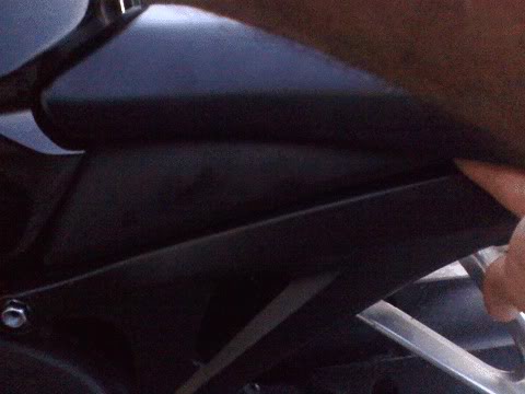
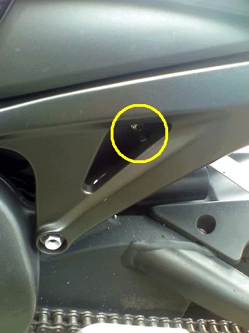
Under the seat there is a plastic triangle. It is only held in by the friction of a post pushed into a rubber grommet. Work your finger behind the back of the triangle...
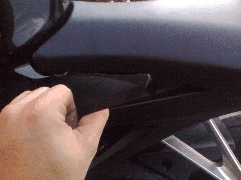
and swing it open like a car door. Repeat for other side.
You will now see the seat screws. If you do not know how to remove them, please, just stop now.
Fan Switch Install
Desired behavior: When the switch is flipped one way, one fan comes on. When flipped the other way, both are on. When centered, all are off. However, they can still come on automatically, just like stock. The ECU tells the right fan to come on at 102.6*C (217*F) and both fans on at 106.2*C (223*F). If the ECU ever signals to turn them on they will still come on, regardless of the switch position.
Circuit behavior: When the switch is flipped one way, a fan relay is connected to battery ground. When flipped the other way, both fan relays are connected to ground. When centered, neither relay is connected.
Parts:
1. Fan switch
2. Solder (silver solder is best)
3. Wire
4. Small zipties
5. Wire loom covering (optional)
6. Small crimp connector for battery terminal
7. Heatshrink tubing (optional)
Tools:
1. Drill to mount switch. A Dremel also works.
2. Soldering iron
3. Wire strippers
4. Small screwdriver or pick to pry with
5. Fan switch. Any DPDT (double-pole, double-throw) switch with a center off will work. It will have 6 terminal connections on the back. If you only want to turn one fan on and off, almost any switch will work. The switch used by me is similar to Radio Shack 275-0664.
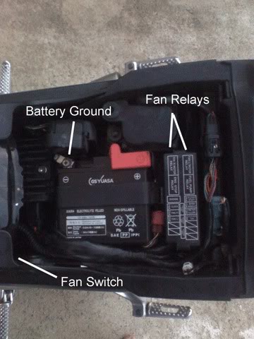
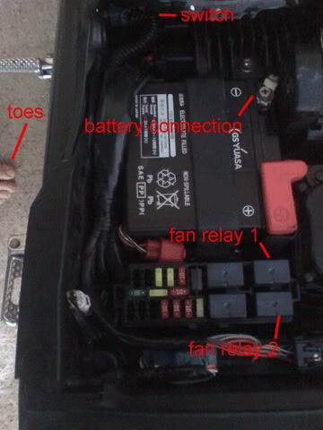
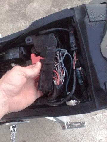
First, an overall idea of what we're doing. This is your underseat area:
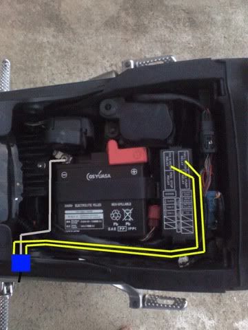
This is our basic wiring route plan:
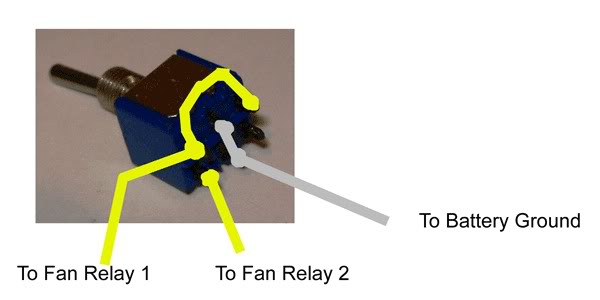
Okay, the first thing we need to do is make our switch. Solder the BATTERY GROUND wire to the TWO CENTER posts, both of them, in the middle. Just strip away enough insulation to reach both posts, lay your wire across both terminals and solder it in place. Radio Shack and other electronic stores sell tiny slip-on crimp connectors that will fit the terminals if your soldering skills are not very good.
Solder ONE short wire between the switch. Look at the picture below. Be sure it clears the ground terminal, otherwise the fan will always be on.
Now solder the two fan wires going to the relays onto their posts. Refer to the picture. It isn’t hard, so don’t worry. Leave the fan wires long.
You now have your fan wiring. Let's go mount the switch.
Go to your bike and look in the front triangle area under the seat/tank. CAREFULLY note where the switch will fit on the inside and where it will clear on the outside. You don't want to have any wire harness in your way and you certainly do not want to drill into any wires. Refer to my installed pic for reference.
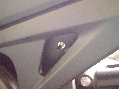
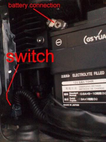
Be sure there's enough room to flip the switch. Once you're sure, drill the hole and test mount the switch. I ended up turning my switch so it toggles back and forth at a slight angle rather than straight up and down. It was easier on my fingers.
With the switch mounted, route the wires to their general areas. Cut the battery connection to length. If you're crimping the connector, you may do so now. I crimp then solder my crimp connections. Cut the relay wires to length.
With the relay wires now clipped to proper lengths, go back to the soldering iron.
Strip the ends of the wire, and with your silver solder (this is important) tin the ends of the wire. For more on soldering and tinning you can Google it, but basically heat the wire until the solder flows into it.
This is done for two reasons:
1. It prevents corrosion. Silver does not corrode the electrical connection like copper will.
2. It makes the end of the wire stiff, so it will not come loose later.
I also solder the ring terminal for the battery connection now.
Back to the bike.
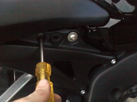
Remove the fusebox cover. On the back of the fusebox, there is a small latch holding the box in place. Insert your screwdriver/pick and unlatch the box. Lift the fusebox up.
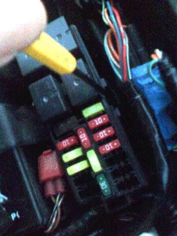
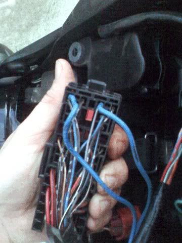
If you flip the fusebox over, you will see the back of all the connectors. You may now push the wire into the proper terminal holes. Please refer to the pic. It is where the fat blue wires are pushed in. When looking at it from underneath the big blue wire on the right goes in the top row in the 3rd hole from the right side. The big blue wire on the left goes in the hole all the way to the far left. Do not reattach your fusebox yet.
With the wires pushed into the back, connect the negative battery wire. Be sure the fan switch is in the center (OFF) position.
Now test your switch. Turn the ignition key to ON position. The RIGHT side fan should come on when the switch is flipped one way; they both should come on when it is flipped the other way. If it's not this way, reverse the fan relay wires.
Okay, you're almost done. Route the switch and wires, ziptie the wires up neatly. Put on the wire loom if you have it.
Now carefully making sure the wires are not in a bad spot under the fusebox, click it in place. The stiff, long wires cannot come out of the connection when the box is latched in place. The underside of the connector is spring-like and will hold a good connection, even under intense vibration. The loomed wire harness can be routed under the OEM wires for an almost invisible install. Just install the switch and put a dab of Locktite on the switch locknut after you get it started.
That's it.
It took longer for me to type/make this page than it took to do the whole thing. Beginning to end it takes about an hour once you have all parts and tools laid out.
Pros:
1. Cheap
2. Easy to use
3. Mostly hidden
4. Much lighter than longer wire setups
5. Wires do not interfere with bodywork, engine, etc...
Cons:
1. Have be able to solder
2. Cost is offset if you have to buy a $20 soldering gun
3. A small hole is made in the plastic battery box
Custom fan switch install, step by step:
Seat removal: (you can skip if you already know how to do this)
Under the seat there is a plastic triangle. It is only held in by the friction of a post pushed into a rubber grommet. Work your finger behind the back of the triangle...
and swing it open like a car door. Repeat for other side.
You will now see the seat screws. If you do not know how to remove them, please, just stop now.
Fan Switch Install
Desired behavior: When the switch is flipped one way, one fan comes on. When flipped the other way, both are on. When centered, all are off. However, they can still come on automatically, just like stock. The ECU tells the right fan to come on at 102.6*C (217*F) and both fans on at 106.2*C (223*F). If the ECU ever signals to turn them on they will still come on, regardless of the switch position.
Circuit behavior: When the switch is flipped one way, a fan relay is connected to battery ground. When flipped the other way, both fan relays are connected to ground. When centered, neither relay is connected.
Parts:
1. Fan switch
2. Solder (silver solder is best)
3. Wire
4. Small zipties
5. Wire loom covering (optional)
6. Small crimp connector for battery terminal
7. Heatshrink tubing (optional)
Tools:
1. Drill to mount switch. A Dremel also works.
2. Soldering iron
3. Wire strippers
4. Small screwdriver or pick to pry with
5. Fan switch. Any DPDT (double-pole, double-throw) switch with a center off will work. It will have 6 terminal connections on the back. If you only want to turn one fan on and off, almost any switch will work. The switch used by me is similar to Radio Shack 275-0664.
First, an overall idea of what we're doing. This is your underseat area:
This is our basic wiring route plan:
Okay, the first thing we need to do is make our switch. Solder the BATTERY GROUND wire to the TWO CENTER posts, both of them, in the middle. Just strip away enough insulation to reach both posts, lay your wire across both terminals and solder it in place. Radio Shack and other electronic stores sell tiny slip-on crimp connectors that will fit the terminals if your soldering skills are not very good.
Solder ONE short wire between the switch. Look at the picture below. Be sure it clears the ground terminal, otherwise the fan will always be on.
Now solder the two fan wires going to the relays onto their posts. Refer to the picture. It isn’t hard, so don’t worry. Leave the fan wires long.
You now have your fan wiring. Let's go mount the switch.
Go to your bike and look in the front triangle area under the seat/tank. CAREFULLY note where the switch will fit on the inside and where it will clear on the outside. You don't want to have any wire harness in your way and you certainly do not want to drill into any wires. Refer to my installed pic for reference.
Be sure there's enough room to flip the switch. Once you're sure, drill the hole and test mount the switch. I ended up turning my switch so it toggles back and forth at a slight angle rather than straight up and down. It was easier on my fingers.
With the switch mounted, route the wires to their general areas. Cut the battery connection to length. If you're crimping the connector, you may do so now. I crimp then solder my crimp connections. Cut the relay wires to length.
With the relay wires now clipped to proper lengths, go back to the soldering iron.
Strip the ends of the wire, and with your silver solder (this is important) tin the ends of the wire. For more on soldering and tinning you can Google it, but basically heat the wire until the solder flows into it.
This is done for two reasons:
1. It prevents corrosion. Silver does not corrode the electrical connection like copper will.
2. It makes the end of the wire stiff, so it will not come loose later.
I also solder the ring terminal for the battery connection now.
Back to the bike.
Remove the fusebox cover. On the back of the fusebox, there is a small latch holding the box in place. Insert your screwdriver/pick and unlatch the box. Lift the fusebox up.
If you flip the fusebox over, you will see the back of all the connectors. You may now push the wire into the proper terminal holes. Please refer to the pic. It is where the fat blue wires are pushed in. When looking at it from underneath the big blue wire on the right goes in the top row in the 3rd hole from the right side. The big blue wire on the left goes in the hole all the way to the far left. Do not reattach your fusebox yet.
With the wires pushed into the back, connect the negative battery wire. Be sure the fan switch is in the center (OFF) position.
Now test your switch. Turn the ignition key to ON position. The RIGHT side fan should come on when the switch is flipped one way; they both should come on when it is flipped the other way. If it's not this way, reverse the fan relay wires.
Okay, you're almost done. Route the switch and wires, ziptie the wires up neatly. Put on the wire loom if you have it.
Now carefully making sure the wires are not in a bad spot under the fusebox, click it in place. The stiff, long wires cannot come out of the connection when the box is latched in place. The underside of the connector is spring-like and will hold a good connection, even under intense vibration. The loomed wire harness can be routed under the OEM wires for an almost invisible install. Just install the switch and put a dab of Locktite on the switch locknut after you get it started.
That's it.
It took longer for me to type/make this page than it took to do the whole thing. Beginning to end it takes about an hour once you have all parts and tools laid out.
Pros:
1. Cheap
2. Easy to use
3. Mostly hidden
4. Much lighter than longer wire setups
5. Wires do not interfere with bodywork, engine, etc...
Cons:
1. Have be able to solder
2. Cost is offset if you have to buy a $20 soldering gun
3. A small hole is made in the plastic battery box
Last edited by RoadiJeff; 02-04-2011 at 09:47 AM.
#2
02-04-2011, 02:26 PM

Super Moderator and Official Welcome Crew Yeti
#3
02-04-2011, 02:40 PM
Senior Member & tensioner mod inventor ROTM WINNER FEB 2013
RoadiJeff,
This is fantastic write up. Very well and concisely put together and could be followed by pretty much anyone.
Just one question (and perhaps I've missed the point). Why would you need/want to do this? What's wrong with just letting the fans come on automatically when the engine gets to the factory set points?
I know people with older bikes have done this to overcome dodgy sensors and other problems related to overheating but your bike is almost new.
#4
02-04-2011, 07:04 PM
I can't take credit for the original write-up of the mod. I just liked the idea and did it to my bike. I copied the author's how-to, re-wrote a few things more clearly and posted it. Compared to the manual fan switch kits I've seen for sale this can all be done for a fraction of the cost.
In my case there are times on a hot summer day where I'm stuck in stop-and-go traffic coming home from work. Although the fans start coming on at 217*F automatically I like being able to reach down and turning them on before the hot engine gets to that point. The heat radiating off the engine as I'm sitting still doesn't seem to be as bad when the fans are keeping things a little cooler.
In my case there are times on a hot summer day where I'm stuck in stop-and-go traffic coming home from work. Although the fans start coming on at 217*F automatically I like being able to reach down and turning them on before the hot engine gets to that point. The heat radiating off the engine as I'm sitting still doesn't seem to be as bad when the fans are keeping things a little cooler.
Last edited by RoadiJeff; 02-04-2011 at 07:46 PM.
#5
02-08-2011, 09:34 PM

Senior Member
Join Date: Dec 2008
Location: Harrisburg, PA
Posts: 513
Likes: 0
Received 0 Likes
on
0 Posts
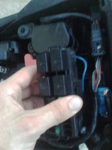
I would like to add to this post for the guys rocking out with the 04-07 1000RR. There is a little different approach. The 04-07 only have 1 fan so you only need a single on/off switch. The relay is located on the front left hand side behind the faring. You do the same as above instructions. One side of the switch is grounded and the other goes into the ground to the relay box. See pictures below.

The box in the middle to the left of the fuse box is the one you need to splice into.

Put the switch wire into the blue/grey wire seen below (my wire going in is green)

Finally the finished product

The box in the middle to the left of the fuse box is the one you need to splice into.
Put the switch wire into the blue/grey wire seen below (my wire going in is green)
Finally the finished product

Thread
Thread Starter
Forum
Replies
Last Post