Cam Chain & Tensioner Replacement
#1
 11-19-2009, 07:21 PM

OK guys this is my 1st write up so we’ll see how it goes. This is the long awaited step by step instruction for replacing the Cam Chain and Tensioner.
In my opinion this job was about 7 out of 10 on difficulty. This took about 3 hours to do. Don’t let that scare you away, I got through it so can you. Of course there are several ways to get this job done, this is just how I did it. If you get hung up, I’ll do my best to help you.
As with all mechanical work I do I offer my 30’ or 30 seconds warranty. After that I claim no responsibility
Special thanks to CBRClassic for assisting with photo placement. Thanks Steve-O!
CAM CHAIN AND TENSIONER REPLACEMENT
Parts you will need:
Valve Cover Gasket
Cam Chain and Master Link – I did a rivet style and recommend it.
Cam Chain Tensioner (I prefer the factory automatic one vs. manual ones)
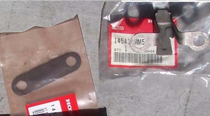
Cam Chain Guide – Top
Cam Chain Guide – Rear (I didn’t do this one and I WISH I would have)
Chain Oiler and Plate (Optional)
Tools you will need:
TORQUE WRENCH – A must unless you have a gift for “knowing” torque values.
Chain Breaker / Rivet Making Tool
Complete Socket Set
2 Vice grip or clamping style tools
ALL TORQUE VALUES ARE IN THE FRONT OF THE MANUAL MAKE SURE YOU LOOK AT THEM!!!!
I recommend you do this job with the bike on a lift. It will save your back from bending over and it’s easier to see the timing marks when you can see them at eye level.
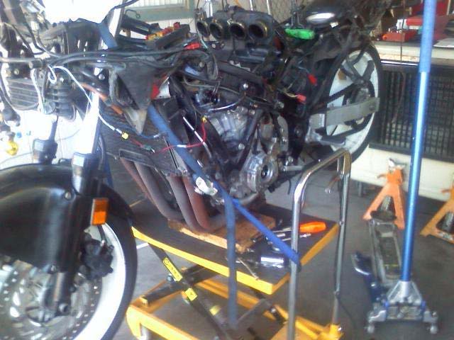
I am going to start from the point of the gas tank & coils / plug wires off the bike.
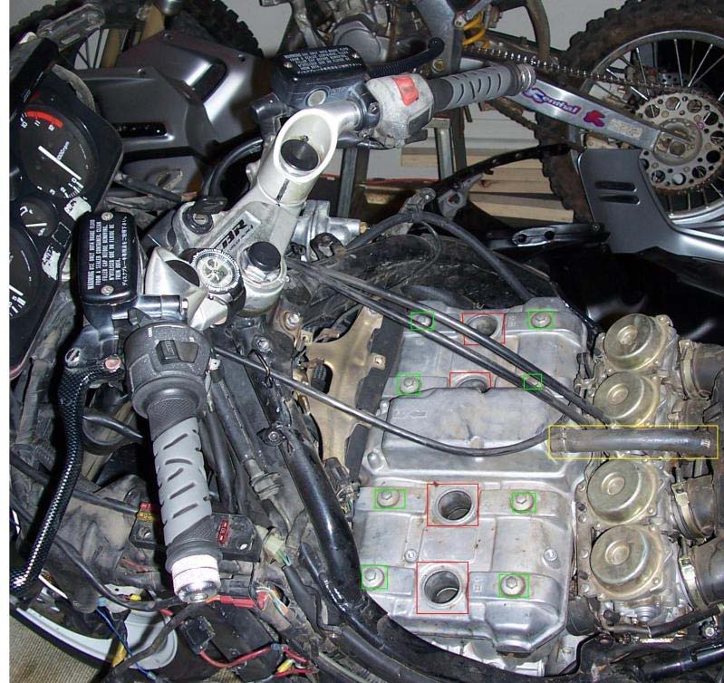
STEP 1 –
Remove the Spark Plugs (Red), Valve Cover Bolts (Green), and Crankcase Breather Tube (Yellow)
Use caution removing the valve cover bolts I snapped one off and had to drill it out and re-tap it
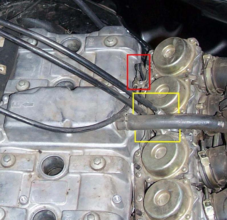
STEP 2 –
Remove the Throttle Cables (Yellow) and Choke Cable (Red)
STEP 3 –
Remove the Valve Cover & Gasket
This is what you should see! Remove the old gasket from the Valve Cover and any other residue from the gasket sealer (marked in Red) from the cylinder head. Make sure ALL residue is removed from the previous gasket.
STEP 4 –
Remove the carburetors. This is not mandatory to do the job, but it makes it a lot easier to have the extra working room later on.
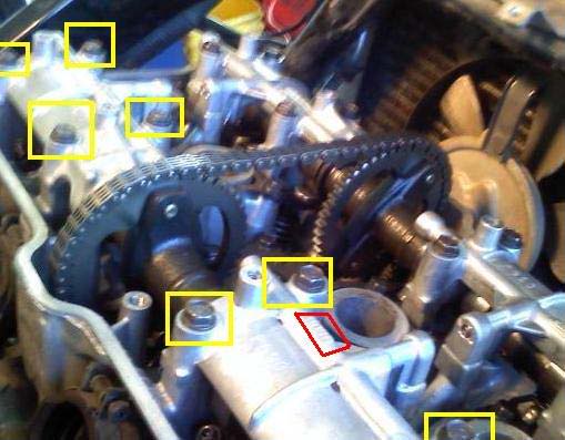
Remove the top chain guide bolts (marked in Yellow). TAKE CARE FROM THIS POINT ON TO NOT ALLOW PARTS, TOOLS, ECT TO FALL DOWN INSIDE THE ENGINE. You can retrieve them later, but you will most likely have to drop the oil pan to get ‘em! The underside should be smooth; non grooved and pliable. Mine was rock hard and grooved.
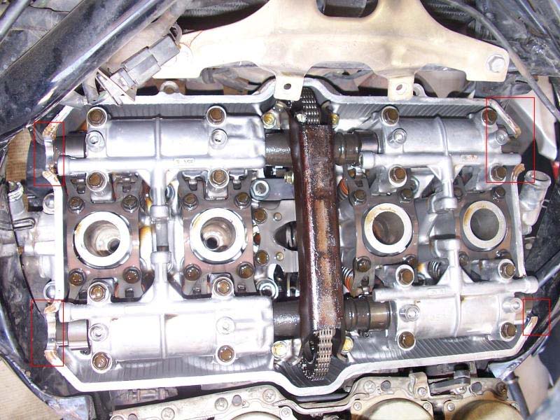
STEP 5 –
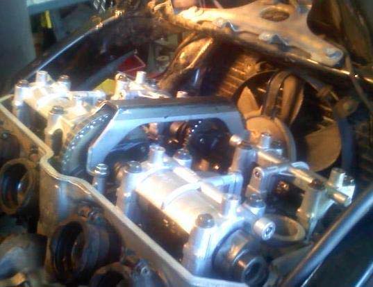
Remove the top cam holder bolts (marked in Yellow) and remove the top of the Cam. Note the cam location (IN L and IN R) for proper re-install location (marked in Red)
STEP 6 –
Unbolt the sprocket from the intake cam. Remove the sprocket & intake cam from the engine. You may need turn the motor manually over by using the timing crank on the lower left part of the motor if the bolts are not in the correct place.
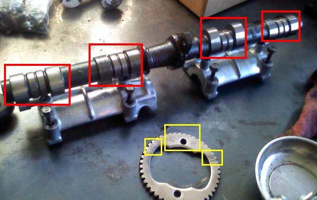
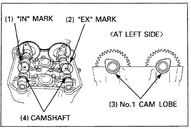
Look at the camshaft. The cam lobes (marked in Red) should be smooth, free from grooves, and straight. Look at the sprocket teeth for ware and damage. Note the IN / EX timing marks on the sprocket and the UP identification (marked in Yellow). You will need these to reset the correct timing later. The sprocket must be UP and facing the LEFT side of the engine when setting the timing. I will go over this later.
STEP 7 –
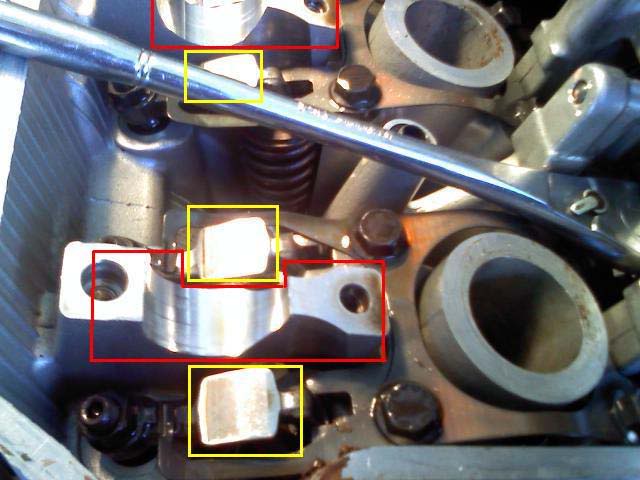
Inspect the bottom side of the cam holder (marked in Red). Like the camshaft it should be smooth and free from grooves. Also inspect the plate (the lifters) the cam lobes roll over (marked in yellow). Again smooth and free from damage. These plates are what press down the valves and valve springs.
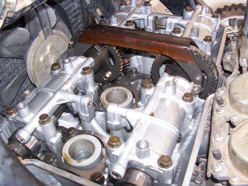
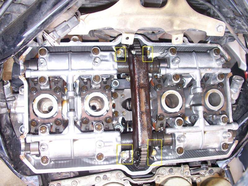
STEP 8 –
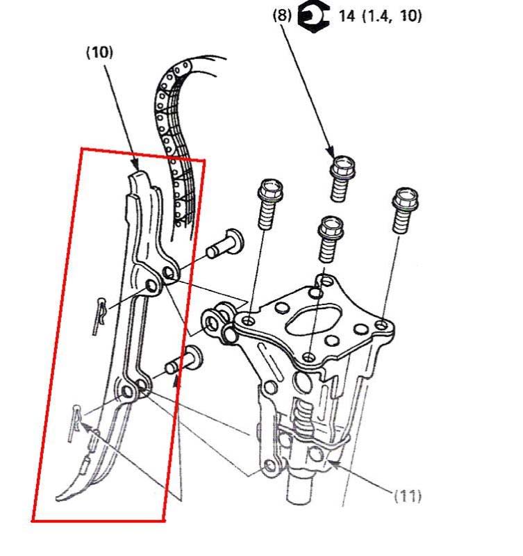
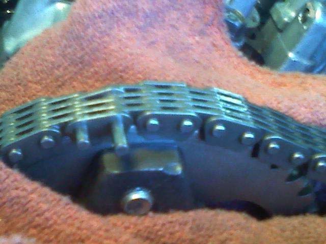
Keep the chain complete, remove the automatic chain tensioner (bolts are marked in Yellow). The REAR CHAIN GUIDE will come out with the tensioner and the chain will still be attached. Remove the 2 pins w/ clips to remove the REAR CHAIN GUIDE. I STRONGLY SUGGEST you replace this guide (marked in Red). It takes the most wear and damage of all 3 guides. The underside should be smooth; non grooved and pliable. Again, mine was rock hard and grooved. The curved end points down if you forget.
HenryM made a very valid point.... Again I cannot express the importance of not letting parts, especially very small ones drop into the engine. It may take a little extra time but could prove very worth it. Prior to removing the "R" clips that secure the pins to the tensioner & chain guide, consider tying them with a length of safety wire. (marked in Red). 1 - this will give you actually something to hold on to, and 2 if you do manage to drop it into the engine it would be MUCH easier to retrieve with a length of wire attached to it (vs looking for a TINY pin) in a very cramped area. We almost dropped one in the engine and the rag caught it. Could have been a disaster. NICE JOB HeneryM
STEP 9 –
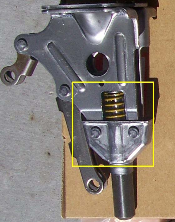
Take the automatic tensioner and pre-oil it before installing. Place the tensioner upright and pour a small amount of oil just above the spring (marked in Yellow). The lower resevior will fill and pump the larger arm to the lower LEFT. The spring will begin to build tension. Pump it until it begins to build pressure.
STEP 10 –
Replace the Chain Oiler Guide and plate. They will be to the front side of the engine just in front of the tensioner.
STEP 11 –
Replace the tensioner and guide. The chain will have to be placed back inside the guide before re-installing the tensioner. Torque to 10 ft-lb
STEP 12 –
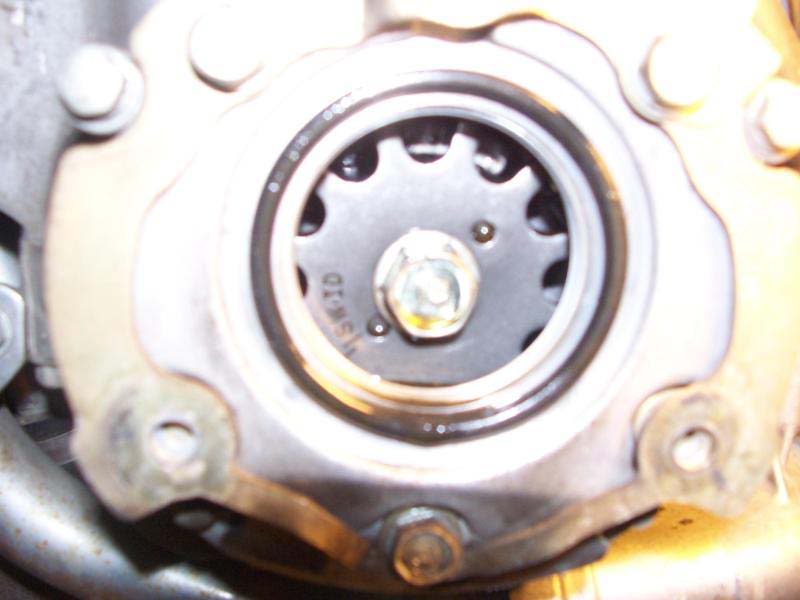
Remove the timing hole cap from the lower left side if the engine (if you haven’t already). This is what you should see; the pulse generator with the timing marks on it.
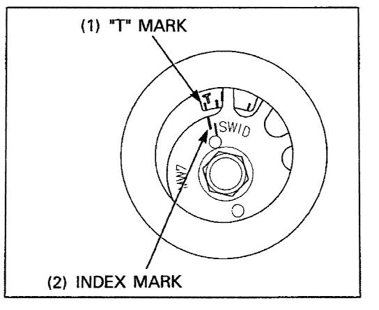
STEP 13 –
Turn the crankshaft COUNTER-CLOCKWISE with spark plugs OUT, until the index mark on the pulse generator matches up with the “ T “ mark on the crank case cover. This places the 1st piston into the correct position to time the engine. It puts it into TDC (top dead center). The motor is now in the correct position to time.
STEP 14 –
Reinstall the intake cam and do not secure the sprocket at this time. Leave it free, but on the shaft. Be sure to oil the cam before replacing it and make sure the cam holders are in the correct position. DO NOT OVER-TIGHTEN these cam holders. Be sure of the correct torque values (10ft-lb). See the picture to get the approximate position they need to be in.
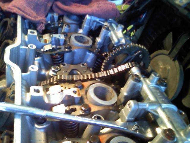
STEP 15 –
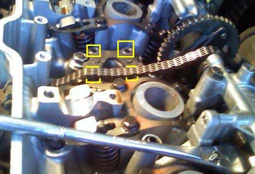
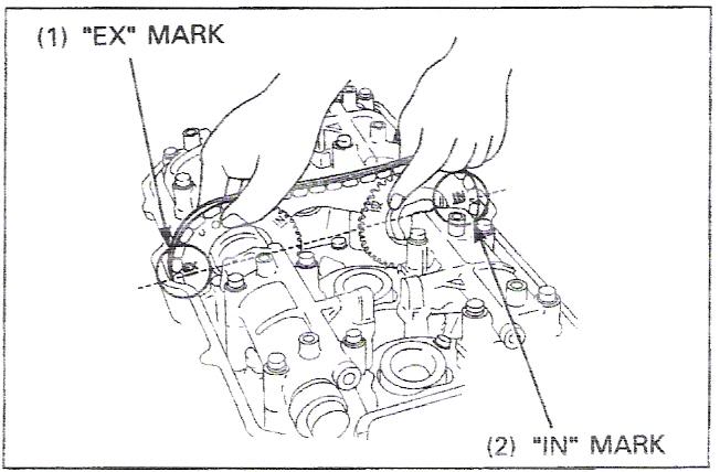
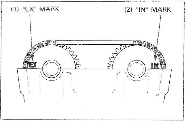
Line the intake and exhaust cam timing marks to the correct location. The EX mark on the exhaust cam needs to line up with the front of the TOP edge of the cylinder head to the front, and the IN mark on the intake cam needs to line up to the rear of the cylinder head. They BOTH need to be in line with each other too. Depress the cam chain tensioner arm with a screwdriver to create slack. Place the OLD timing chain back on the sprockets to keep the cams in the correct place once set. Ensure the cam chain is on the crankshaft sprocket down inside the engine. See the pictures to show proper timing placement.
STEP 16 –
When the timing marks are in the correct position with the cam chain on the sprockets, recheck the pulse generator to ensure the timing mark is still in the correct position.
When you have the timing marks in the correct position, bolt the intake sprocket back into place. Use a thread locking agent and torque to 12 ft-lb.
Turn the crankshaft COUNTER-CLOCKWISE to verify the timing marks meet up when the motor is turning. There is a 2:1 ratio from the cam sprocket’s mark to the pulse generator mark. Meaning as you turn the crankshaft the 1st time the cam marks line up as timed, the the pulse generator will not be lined up until the sprockets make another full revolution. I hope that makes sense. The 1st time we turned the motor I was caught off guard; the cams were dead on while the pulse generator was off. One more revolution, everything was perfect. Consistently every 1st turn the pulse generator was off and 2nd everything is perfect. My mechanic friend said this is because there a 2:1 ratio from the pulse generator to the cams.
Pics relinked 10/22/2012
In my opinion this job was about 7 out of 10 on difficulty. This took about 3 hours to do. Don’t let that scare you away, I got through it so can you. Of course there are several ways to get this job done, this is just how I did it. If you get hung up, I’ll do my best to help you.
As with all mechanical work I do I offer my 30’ or 30 seconds warranty. After that I claim no responsibility
Special thanks to CBRClassic for assisting with photo placement. Thanks Steve-O!
CAM CHAIN AND TENSIONER REPLACEMENT
Parts you will need:
Valve Cover Gasket
Cam Chain and Master Link – I did a rivet style and recommend it.
Cam Chain Tensioner (I prefer the factory automatic one vs. manual ones)
Cam Chain Guide – Top
Cam Chain Guide – Rear (I didn’t do this one and I WISH I would have)
Chain Oiler and Plate (Optional)
Tools you will need:
TORQUE WRENCH – A must unless you have a gift for “knowing” torque values.
Chain Breaker / Rivet Making Tool
Complete Socket Set
2 Vice grip or clamping style tools
ALL TORQUE VALUES ARE IN THE FRONT OF THE MANUAL MAKE SURE YOU LOOK AT THEM!!!!
I recommend you do this job with the bike on a lift. It will save your back from bending over and it’s easier to see the timing marks when you can see them at eye level.
I am going to start from the point of the gas tank & coils / plug wires off the bike.
STEP 1 –
Remove the Spark Plugs (Red), Valve Cover Bolts (Green), and Crankcase Breather Tube (Yellow)
Use caution removing the valve cover bolts I snapped one off and had to drill it out and re-tap it
STEP 2 –
Remove the Throttle Cables (Yellow) and Choke Cable (Red)
STEP 3 –
Remove the Valve Cover & Gasket
This is what you should see! Remove the old gasket from the Valve Cover and any other residue from the gasket sealer (marked in Red) from the cylinder head. Make sure ALL residue is removed from the previous gasket.
STEP 4 –
Remove the carburetors. This is not mandatory to do the job, but it makes it a lot easier to have the extra working room later on.
Remove the top chain guide bolts (marked in Yellow). TAKE CARE FROM THIS POINT ON TO NOT ALLOW PARTS, TOOLS, ECT TO FALL DOWN INSIDE THE ENGINE. You can retrieve them later, but you will most likely have to drop the oil pan to get ‘em! The underside should be smooth; non grooved and pliable. Mine was rock hard and grooved.
STEP 5 –
Remove the top cam holder bolts (marked in Yellow) and remove the top of the Cam. Note the cam location (IN L and IN R) for proper re-install location (marked in Red)
STEP 6 –
Unbolt the sprocket from the intake cam. Remove the sprocket & intake cam from the engine. You may need turn the motor manually over by using the timing crank on the lower left part of the motor if the bolts are not in the correct place.
Look at the camshaft. The cam lobes (marked in Red) should be smooth, free from grooves, and straight. Look at the sprocket teeth for ware and damage. Note the IN / EX timing marks on the sprocket and the UP identification (marked in Yellow). You will need these to reset the correct timing later. The sprocket must be UP and facing the LEFT side of the engine when setting the timing. I will go over this later.
STEP 7 –
Inspect the bottom side of the cam holder (marked in Red). Like the camshaft it should be smooth and free from grooves. Also inspect the plate (the lifters) the cam lobes roll over (marked in yellow). Again smooth and free from damage. These plates are what press down the valves and valve springs.
STEP 8 –
Keep the chain complete, remove the automatic chain tensioner (bolts are marked in Yellow). The REAR CHAIN GUIDE will come out with the tensioner and the chain will still be attached. Remove the 2 pins w/ clips to remove the REAR CHAIN GUIDE. I STRONGLY SUGGEST you replace this guide (marked in Red). It takes the most wear and damage of all 3 guides. The underside should be smooth; non grooved and pliable. Again, mine was rock hard and grooved. The curved end points down if you forget.
HenryM made a very valid point.... Again I cannot express the importance of not letting parts, especially very small ones drop into the engine. It may take a little extra time but could prove very worth it. Prior to removing the "R" clips that secure the pins to the tensioner & chain guide, consider tying them with a length of safety wire. (marked in Red). 1 - this will give you actually something to hold on to, and 2 if you do manage to drop it into the engine it would be MUCH easier to retrieve with a length of wire attached to it (vs looking for a TINY pin) in a very cramped area. We almost dropped one in the engine and the rag caught it. Could have been a disaster. NICE JOB HeneryM
STEP 9 –
Take the automatic tensioner and pre-oil it before installing. Place the tensioner upright and pour a small amount of oil just above the spring (marked in Yellow). The lower resevior will fill and pump the larger arm to the lower LEFT. The spring will begin to build tension. Pump it until it begins to build pressure.
STEP 10 –
Replace the Chain Oiler Guide and plate. They will be to the front side of the engine just in front of the tensioner.
STEP 11 –
Replace the tensioner and guide. The chain will have to be placed back inside the guide before re-installing the tensioner. Torque to 10 ft-lb
STEP 12 –
Remove the timing hole cap from the lower left side if the engine (if you haven’t already). This is what you should see; the pulse generator with the timing marks on it.
STEP 13 –
Turn the crankshaft COUNTER-CLOCKWISE with spark plugs OUT, until the index mark on the pulse generator matches up with the “ T “ mark on the crank case cover. This places the 1st piston into the correct position to time the engine. It puts it into TDC (top dead center). The motor is now in the correct position to time.
STEP 14 –
Reinstall the intake cam and do not secure the sprocket at this time. Leave it free, but on the shaft. Be sure to oil the cam before replacing it and make sure the cam holders are in the correct position. DO NOT OVER-TIGHTEN these cam holders. Be sure of the correct torque values (10ft-lb). See the picture to get the approximate position they need to be in.
STEP 15 –
Line the intake and exhaust cam timing marks to the correct location. The EX mark on the exhaust cam needs to line up with the front of the TOP edge of the cylinder head to the front, and the IN mark on the intake cam needs to line up to the rear of the cylinder head. They BOTH need to be in line with each other too. Depress the cam chain tensioner arm with a screwdriver to create slack. Place the OLD timing chain back on the sprockets to keep the cams in the correct place once set. Ensure the cam chain is on the crankshaft sprocket down inside the engine. See the pictures to show proper timing placement.
STEP 16 –
When the timing marks are in the correct position with the cam chain on the sprockets, recheck the pulse generator to ensure the timing mark is still in the correct position.
When you have the timing marks in the correct position, bolt the intake sprocket back into place. Use a thread locking agent and torque to 12 ft-lb.
Turn the crankshaft COUNTER-CLOCKWISE to verify the timing marks meet up when the motor is turning. There is a 2:1 ratio from the cam sprocket’s mark to the pulse generator mark. Meaning as you turn the crankshaft the 1st time the cam marks line up as timed, the the pulse generator will not be lined up until the sprockets make another full revolution. I hope that makes sense. The 1st time we turned the motor I was caught off guard; the cams were dead on while the pulse generator was off. One more revolution, everything was perfect. Consistently every 1st turn the pulse generator was off and 2nd everything is perfect. My mechanic friend said this is because there a 2:1 ratio from the pulse generator to the cams.
Pics relinked 10/22/2012
Last edited by Sprock; 10-22-2012 at 08:37 AM. Reason: small goof up (updating the Barons Pics) Sprock 10/2012
#2
11-19-2009, 09:38 PM
CONTINUED
STEP 17 –
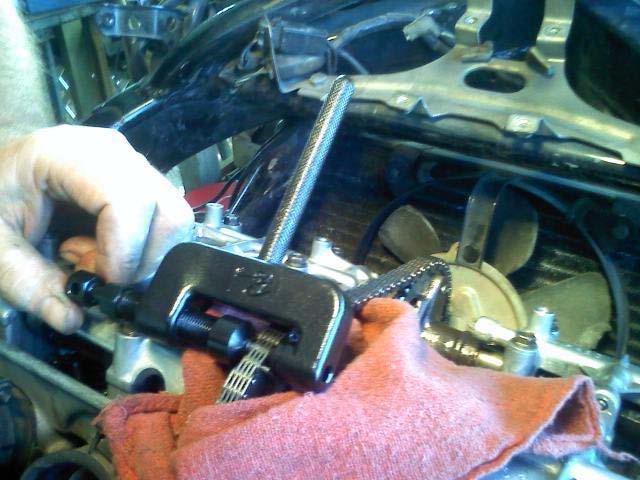
Now the cam chain needs to be replaced. Use your chain breaker and break the chain. Place a rag down below to prevent the pin from falling down into the engine. The pin almost fell in when we did this.
DO NOT LET THE CHAIN FALL DOWN INTO THE ENGINE!
STEP 18 –
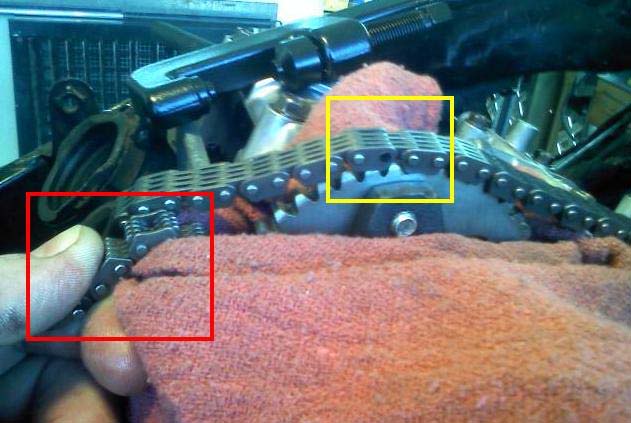
Attach the new cam chain to the old chain (marked in Yellow). Hold on to the other end of the chain or attach vice grips to prevent to chain from falling in (marked in Red). We pressed in an old pin from the old chain to use it to run it through the engine. It may have been overkill to do this, but we did not want to run the chance of the chains coming apart while them running over the crankshaft and through the engine.
This is where removing the carburetors makes life easier if you did it earlier.
STEP 19 –
Feed the chain through. Keep strong tension on the new chain to prevent slack and the sprockets jumping (throwing the timing off) as the chain is fed through. Turn the crankshaft SLOWLY, COUNTER-CLOCKWISE and the cams are going to turn. Going slow will help to prevent the sprockets from jumping. The exhaust cam will pull the chain in, and it will feed over the crankshaft, and out the intake cam. If you hold a proper amount of tension and assist the chain through, the cams will turn with the new chain and it will not have to be re-timed when the new chain is in. IF a sprocket jumps while turning the crank address it immediately and again you should have not to re-time. If it jumps a tooth, simply turn it back a tooth.
STEP 20 –
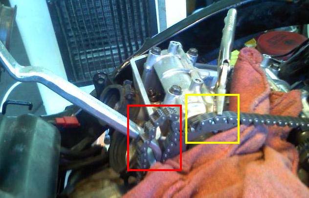
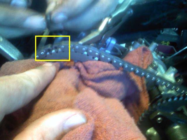
The old cam chain should have now come through the intake side and it needs to be removed from the new cam chain. Secure the new chain to the intake sprocket (marked in Yellow) and secure the chain to remove the old chain (marked in Red).
STEP 21 –
Leave the chain secured to the sprocket. The chain now is free from the old chain and is ready to be riveted. When we did this, we came up 2 links short. At first we thought the chain was too short. What happened was the chain tensioner was fully opened up so the chain was under tension and came up short. To rectify the problem, we placed a screwdriver on the cam tensioner tension arm to release the tension and then there was plenty of slack. The chain now matches up perfectly (marked in Yellow), it is properly tensioned, and the tensioner has plenty of spring left to keep tension up over time.
Use your riveting tool to make the master link connection.
Re-check your timing.
STEP 22 –
Install the new top chain guide and torque properly.
STEP 23 –
Install the carburetors and valve cover with new gasket. Replace spark plugs. Place choke and throttle cables back on. Reinstall coils, plug wires, and gas tank.
Start bike and check for smooth running and timing. The bike may take a few tries to start to allow fuel to get back to the carbs and mixed to the engine. The chain may also rattle for a minute or two. As long as the motor is running smooth (correctly timed) the rattle will subside soon. The rattle is due to the chain and chain oiler being dry and picking up oil from the pan (kinda like when you change the oil your car, the 1st few seconds the oil psi guage will stay low untill the engine picks up oil from the pan).
That should be it! I hope this helped!
edit 10/22/2012 : In our thoughts Mike - gone but never forgotten man.
STEP 17 –
Now the cam chain needs to be replaced. Use your chain breaker and break the chain. Place a rag down below to prevent the pin from falling down into the engine. The pin almost fell in when we did this.
DO NOT LET THE CHAIN FALL DOWN INTO THE ENGINE!
STEP 18 –
Attach the new cam chain to the old chain (marked in Yellow). Hold on to the other end of the chain or attach vice grips to prevent to chain from falling in (marked in Red). We pressed in an old pin from the old chain to use it to run it through the engine. It may have been overkill to do this, but we did not want to run the chance of the chains coming apart while them running over the crankshaft and through the engine.
This is where removing the carburetors makes life easier if you did it earlier.
STEP 19 –
Feed the chain through. Keep strong tension on the new chain to prevent slack and the sprockets jumping (throwing the timing off) as the chain is fed through. Turn the crankshaft SLOWLY, COUNTER-CLOCKWISE and the cams are going to turn. Going slow will help to prevent the sprockets from jumping. The exhaust cam will pull the chain in, and it will feed over the crankshaft, and out the intake cam. If you hold a proper amount of tension and assist the chain through, the cams will turn with the new chain and it will not have to be re-timed when the new chain is in. IF a sprocket jumps while turning the crank address it immediately and again you should have not to re-time. If it jumps a tooth, simply turn it back a tooth.
STEP 20 –
The old cam chain should have now come through the intake side and it needs to be removed from the new cam chain. Secure the new chain to the intake sprocket (marked in Yellow) and secure the chain to remove the old chain (marked in Red).
STEP 21 –
Leave the chain secured to the sprocket. The chain now is free from the old chain and is ready to be riveted. When we did this, we came up 2 links short. At first we thought the chain was too short. What happened was the chain tensioner was fully opened up so the chain was under tension and came up short. To rectify the problem, we placed a screwdriver on the cam tensioner tension arm to release the tension and then there was plenty of slack. The chain now matches up perfectly (marked in Yellow), it is properly tensioned, and the tensioner has plenty of spring left to keep tension up over time.
Use your riveting tool to make the master link connection.
Re-check your timing.
STEP 22 –
Install the new top chain guide and torque properly.
STEP 23 –
Install the carburetors and valve cover with new gasket. Replace spark plugs. Place choke and throttle cables back on. Reinstall coils, plug wires, and gas tank.
Start bike and check for smooth running and timing. The bike may take a few tries to start to allow fuel to get back to the carbs and mixed to the engine. The chain may also rattle for a minute or two. As long as the motor is running smooth (correctly timed) the rattle will subside soon. The rattle is due to the chain and chain oiler being dry and picking up oil from the pan (kinda like when you change the oil your car, the 1st few seconds the oil psi guage will stay low untill the engine picks up oil from the pan).
That should be it! I hope this helped!
edit 10/22/2012 : In our thoughts Mike - gone but never forgotten man.
Last edited by Sprock; 10-22-2012 at 09:25 AM. Reason: reinsert the Baron's missing pics
 well done !!!
#4
11-19-2009, 10:45 PM

Senior Member & 2010 ROTY
#5
11-19-2009, 11:05 PM

Administrator - Retired
#7
11-20-2009, 07:10 AM

Senior Member
Join Date: Jan 2008
Location: Melbourne, Australia
Posts: 124
Likes: 0
Received 0 Likes
on
0 Posts
#8
11-20-2009, 07:36 AM


#10
11-21-2009, 05:31 AM

Hi Michael. A sensational write-up!
Many thanks for all the time, thought and effort you put into this write-up for the benefit of us all. As you can see from all the response posts we are all indebted to you. Thank you.
You have now set a new standard of "How To"'s that will challenge us all... A new standard - a new era!!!!
Many thanks for all the time, thought and effort you put into this write-up for the benefit of us all. As you can see from all the response posts we are all indebted to you. Thank you.
You have now set a new standard of "How To"'s that will challenge us all...
Last edited by Naga_Thai; 11-21-2009 at 05:33 AM.