Hidden Radar Detector
#1
 09-18-2009, 11:10 AM


Join Date: Aug 2009
Location: Rolla, MO
Posts: 48
Likes: 0
Received 0 Likes
on
0 Posts
Out of curiosity, who would like to see instructions (with pictures) on how to do a custom radar detector installation into the nose of an F3?
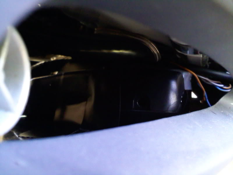
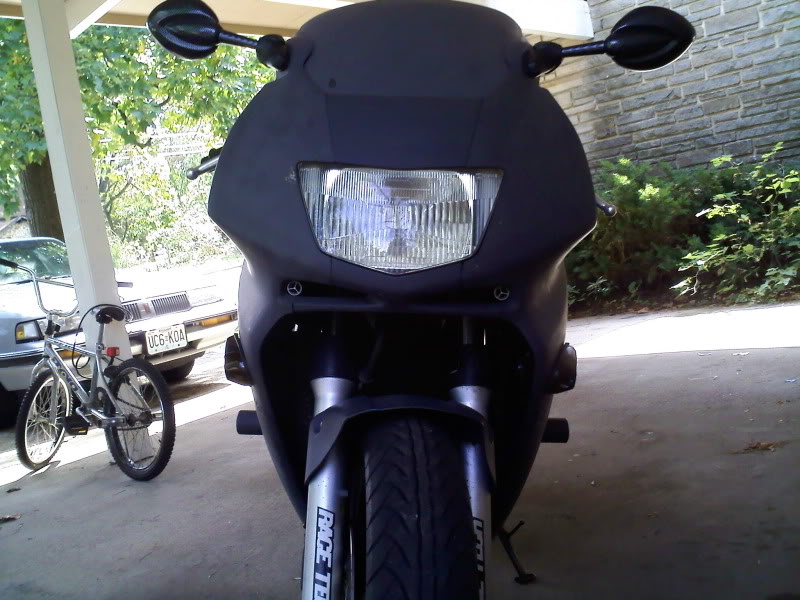
It's just a typical car radar/laser detector but I modified it to run off of the bikes electrical system and turn off when you shut the bike off. The detector itself is completely hidden behind the nose of the bike and still detects radar signals perfectly (radar penetrates plastic easily.)
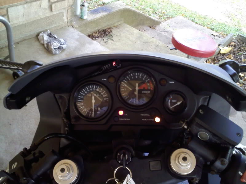
The display is mounted separately from the rest of the detector on my instrument panel above my speedo.
(I posted this here as well as in the F3 section because This should work for an F1, F2, and F3. It might work for newer cbrs as well, but I don't know if they have any dead empty space behind plastic up in the front of the bike.)
It's just a typical car radar/laser detector but I modified it to run off of the bikes electrical system and turn off when you shut the bike off. The detector itself is completely hidden behind the nose of the bike and still detects radar signals perfectly (radar penetrates plastic easily.)
The display is mounted separately from the rest of the detector on my instrument panel above my speedo.
(I posted this here as well as in the F3 section because This should work for an F1, F2, and F3. It might work for newer cbrs as well, but I don't know if they have any dead empty space behind plastic up in the front of the bike.)
#3
09-18-2009, 12:14 PM
Join Date: Aug 2009
Location: Rolla, MO
Posts: 48
Likes: 0
Received 0 Likes
on
0 Posts
Things you'll need:
-Working 12 volt radar detector
-15 watt (or lower maybe) soldering iron
-Thinnest solder you can find
-Very light gauge stranded copper wire (not one solid wire preferably)
-Heat shrink tubing
-Multimeter
-12v DC power supply (could use power adapter or a battery)
Before you go and buy anything other than the radar detector (assuming you didn't already have an old one to use) you should take the radar detector apart down to the base circuit board and look for a way to unsolder all the pins holding the LED display in place. If it doesn't look like you could remove all the joints and solder wires on to them, then don't even bother with that detector.
You should also take note of the amount of connections that the LED has to the circuit board. Mine had 13, which I later found out was precisely the amount of wires combined in a USB cable and an Ethernet cable. I'd say if there's much more than 15 connection points total, you're going to have a hell of a time removing the LED and soldering wires to both the circuit board and the display itself.
After you've done this and determined that you don't have a million points to solder, you can go ahead and unsolder the 12v power jack from the board. Make sure that you determine the polarity of the power jack before you remove it and take note of the fact that it will probably have 3 connections to unsolder, only two of which are actually powered.
When unsoldering the LED screen, make sure you remove all the excess solder before you try to push it out of its mounts. If you don't do this and/or it isn't reasonably easy to push out the LED, you could break it and then ruin the whole project.
Once you have the LED screen and power jack unsoldered from the board, you're ready to mock the radar detector and screen wherever you would like to put them. I chose to put the radar detector behind the nose of the bike, which contrary to what my second picture above this looks to be showing, you'd have to have your face right up next to the side of the front plastics to actually even see the detector and wires.
I chose to mount the screen above my speedo. You can put it wherever the hell you want to, but I chose there because it's constantly within my peripheral vision while I'm riding.
#4
09-18-2009, 01:54 PM
Join Date: Aug 2009
Location: Rolla, MO
Posts: 48
Likes: 0
Received 0 Likes
on
0 Posts
So now you're ready to bridge the gap between wherever you wanted to put the display with wherever you wanted to put the radar detector. Go out and find some of the thinnest wire possible to do this, and try to make sure it's stranded and not solid core since stranded will absorb and stick to the solder better.
I had 13 connections to bridge so I chose a black Ethernet cable containing 8 small wires along with a black USB cable containing 5 small wires. I know there's better stuff out there but I had to work with what I had. I also purchased some 24 gauge two strand wire to use as the power cable for the detector.
Unless you know exactly how much wire it's going to take to get from point A to B, you're going to need to create connection points at each end after about 6 inches of wire. So, assuming you're not a mathmagician with wires, cut 6 inches for both sides and strip both ends of the wire, making sure that the end you're going to solder only has about a millimeter or two actually stripped off.
Now the fun part. Solder all the wires to each individual connection making sure to match the colors for both sides. This takes forever to do, and you'll probably f**k up at some point in time, so just take a deep breath, take your time, and listen to some calm, relaxing music (which for me is melodic death metal and acid trance...lol)
Here's some pictures of what things should be looking like:
That's where I soldered the two strand 24 gauge wire into where the power jack used to be.
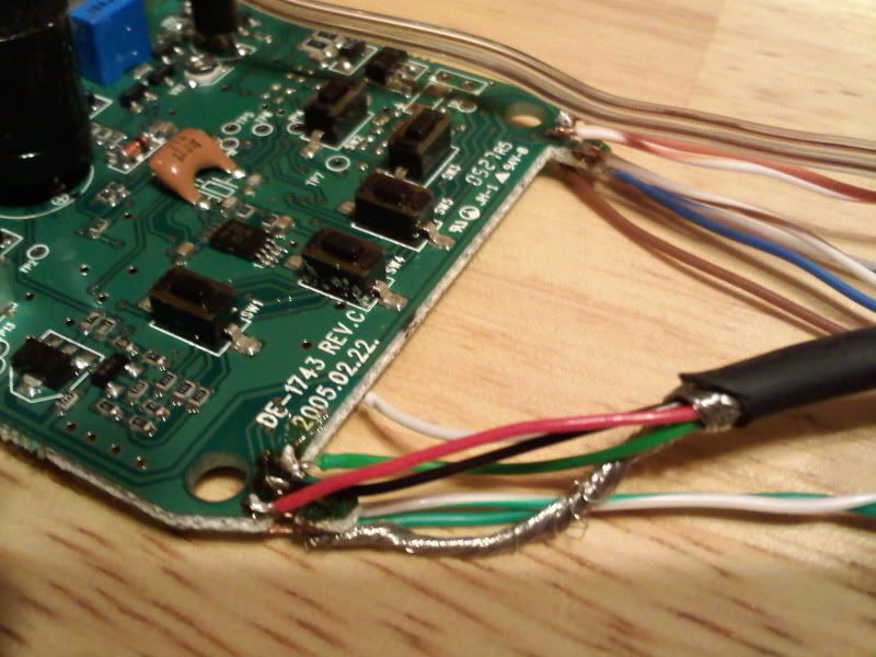
Here's a few of the re-soldered joints on the circuit board side of the LED.
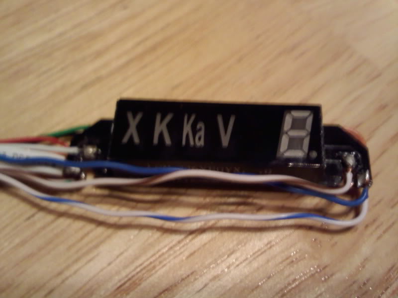
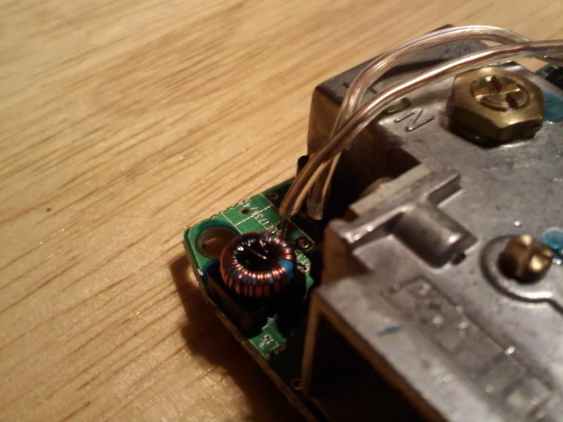
Here's the front of the LED screen after I re-soldered all the junctions. There were wires to solder on both the front and back of this board as well as on the detector circuit board.
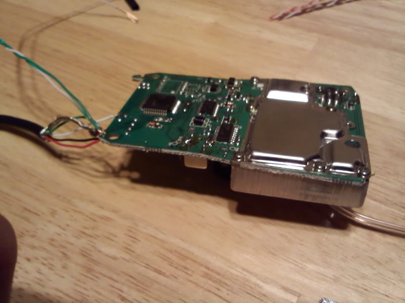
Underside of the radar detector circuit board before all the wires were soldered on. Note how small the gauge is that I've been using. You don't want to use anything too heavy because those small points will short out if you do. You'll also have trouble routing a heavy cable through the front of the bike.
I had 13 connections to bridge so I chose a black Ethernet cable containing 8 small wires along with a black USB cable containing 5 small wires. I know there's better stuff out there but I had to work with what I had. I also purchased some 24 gauge two strand wire to use as the power cable for the detector.
Unless you know exactly how much wire it's going to take to get from point A to B, you're going to need to create connection points at each end after about 6 inches of wire. So, assuming you're not a mathmagician with wires, cut 6 inches for both sides and strip both ends of the wire, making sure that the end you're going to solder only has about a millimeter or two actually stripped off.
Now the fun part. Solder all the wires to each individual connection making sure to match the colors for both sides. This takes forever to do, and you'll probably f**k up at some point in time, so just take a deep breath, take your time, and listen to some calm, relaxing music (which for me is melodic death metal and acid trance...lol)
Here's some pictures of what things should be looking like:
That's where I soldered the two strand 24 gauge wire into where the power jack used to be.
Here's a few of the re-soldered joints on the circuit board side of the LED.
Here's the front of the LED screen after I re-soldered all the junctions. There were wires to solder on both the front and back of this board as well as on the detector circuit board.
Underside of the radar detector circuit board before all the wires were soldered on. Note how small the gauge is that I've been using. You don't want to use anything too heavy because those small points will short out if you do. You'll also have trouble routing a heavy cable through the front of the bike.
#5
09-18-2009, 02:06 PM
Join Date: Aug 2009
Location: Rolla, MO
Posts: 48
Likes: 0
Received 0 Likes
on
0 Posts
Now that you've got everything soldered back together, you need to connect all the wires, making sure you match the colors back together. Find your 12 volt DC power supply and plug in your power cable for the detector. Hold your breath!
If you did everything right, the detector and now separate screen should fire up without any dead pixels/lights. If it doesn't, curse yourself for ever being born and shame on you for being so terrible with a soldering iron. Seriously though, you probably either just crossed a wire somewhere or had a soldering joint break while you were handling it.
Now that everything works, go find some ABS cement. I don't care where or how you get it, and I don't care about the fact that I forgot to mention you need a jar of the stuff... lol. Go back and dab ABS cement over all the soldering connections you just made. Really pour that stuff on there too... You don't want your soldered connections to break while you're riding resulting in you having to tear everything apart and solder it again.
Give everything some time to dry. If I were you, I'd go outside and play and finish the second part the next day because at this point, you're probably already several hours into the project.
Here's some pictures!
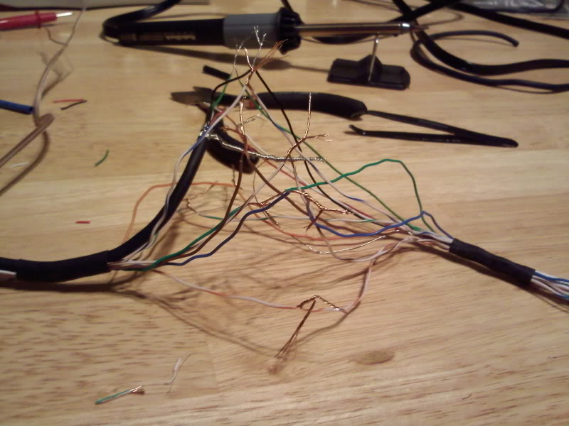
Ghetto wires twisted for the test setup. You're going to go back and disconnect them again, so don't crimp them or anything just yet
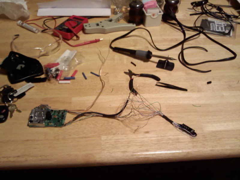
Another picture of the test setup. Notice how I don't have ABS cement on any connections yet? Don't put any on there before you test it or you'll kick yourself in the **** for doing it when one of the connections is bad.
If you did everything right, the detector and now separate screen should fire up without any dead pixels/lights. If it doesn't, curse yourself for ever being born and shame on you for being so terrible with a soldering iron. Seriously though, you probably either just crossed a wire somewhere or had a soldering joint break while you were handling it.
Now that everything works, go find some ABS cement. I don't care where or how you get it, and I don't care about the fact that I forgot to mention you need a jar of the stuff... lol. Go back and dab ABS cement over all the soldering connections you just made. Really pour that stuff on there too... You don't want your soldered connections to break while you're riding resulting in you having to tear everything apart and solder it again.
Give everything some time to dry. If I were you, I'd go outside and play and finish the second part the next day because at this point, you're probably already several hours into the project.
Here's some pictures!
Ghetto wires twisted for the test setup. You're going to go back and disconnect them again, so don't crimp them or anything just yet
Another picture of the test setup. Notice how I don't have ABS cement on any connections yet? Don't put any on there before you test it or you'll kick yourself in the **** for doing it when one of the connections is bad.

#7
09-18-2009, 05:50 PM
Join Date: Aug 2009
Location: Rolla, MO
Posts: 48
Likes: 0
Received 0 Likes
on
0 Posts

Thread
Thread Starter
Forum
Replies
Last Post

